Migrating from Traditional to Flexible NetFlow-CISCO IOS -IOS XE
Aside
Migrating from Traditional to Flexible NetFlow
Emmanuel Tychon Technical Marketing Engineer
Network Software & Systems Technology Group

|
Contents [hide] |
Why Migrate to Flexible NetFlow?
If you are reading this document, you’re either already convinced or curious about the potential advantages that Cisco’s Flexible NetFlow will bring.
For us at Cisco, this is a normal transition, and some new platforms and software releases will exclusively support Flexible NetFlow.
(Such as “IOS XE" , “ASR" ) .
As the time goes on, we will never come back to Traditional NetFlow, so it’s better to get prepared for the transition.
In this document we will call “Traditional NetFlow" everything that is not “Flexible NetFlow".
Some might simply think of using Flexible NetFlow the same way they were using Traditional NetFlow: that is, with the same flow record and by exporting with NetFlow v5 or NetFlow v9.
Although this is possible, we believe it’s an interim solution to enable a smooth migration that does not require any modification on existing collectors, but we don’t recommend going down that road as it won’t allow you to take advantage of the full capabilities of Flexible NetFlow.
Traditional NetFlow used a fixed seven tupple of IP information to identify a flow most of the time.
A big advantage of the new Flexible NetFlow concept is that the flow can be user defined. The benefits of Flexible NetFlow include:
- Flexible NetFlow will integrate with NBAR to provide application visibility rather than just flow visibility. This position Flexible NetFlow as a unique tool to differentiate and meter applications right from within the network.
- Because only interesting flows with selected key-fields will be analyzed, Flexible NetFlow generally offers better performance, scalability, and aggregation of flow information.
- Enhanced flow infrastructure for security monitoring and distributed DoS detection and identification.
- New information from packets to adapt flow information to a particular service or operation in the network. The flow information available will be customizable by Flexible NetFlow users.
- Extensive use of Cisco’s flexible and extensible NetFlow Version 9 export format.
- A comprehensive IP accounting feature that can be used to replace many accounting features, such as IP accounting, BGP Policy Accounting, and persistent caches.
- New high-end platforms such as Cisco Catalyst’ 6000 with EARL8, Cisco Catalyst 4000 with K10, next generation of Cisco Catalyst 3000, and so on will exclusively support Flexible NetFlow.
Traditional NetFlow allows you to understand what the network is doing and thus to optimize network design and reduce operational costs. With Flexible NetFlow the notion of flow goes beyond Layers 2/3/4. It gives you greater visibility and allows you to understand network behavior with more efficiency, with specific flow information tailored for various services used in the network.
What’s Changing When Migrating to Flexible NetFlow?
We have tried to reduce the pain for you to transition from traditional NetFlow to Flexible NetFlow; however, a few points might require more attention.
New Data Export Protocol
The export protocol of choice for Flexible NetFlow is NetFlow v9 export protocol, but unfortunately and to date, NetFlow v5 has been a much more widely used protocol because legacy Cisco IOS Software images are still around, supported NetFlow v5 export protocol only, and worked very well.
As mentioned in the previous section, Flexible NetFlow can also be configured to export some predefined flow records using the NetFlow v5 protocol format for backward compatibility.
As we transition to Flexible NetFlow’s new model, one gains the ability to select key fields and nonkey fields, to export many different fields (for example, packet fragments), to export MPLS labels or BGP next-hop fields, and so on. These fields cannot be transmitted over NetFlow v5 and can only be exported with a protocol that is as flexible as NetFlow v9, or later, IPFIX.
The main feature of NetFlow Version 9 export format is that it is template-based. A template describes a NetFlow record format and attributes of the fields (such as type and length) within the record. The router assigns each template an ID, which is communicated to the NetFlow Collection Engine along with the template description. The template ID is used for all further communication from the router to the NetFlow Collection Engine. (See Table 1.)
Table 1 : Overview of protocols per version of NetFlow
|
NetFlow Metering Process |
Information Elements |
NetFlow Export Protocol |
Transport Protocol |
|
Traditional NetFlow |
Traditional |
NetFlow Versions 5 and 9 |
UDP |
|
Traditional NetFlow |
New (IPv6, Multicast) |
NetFlow Version 9 |
UDP/SCTP |
|
Flexible NetFlow |
Predefined Record for Traditional NetFlow |
NetFlow Versions 5 and 9 |
UDP |
|
Flexible NetFlow |
Other |
NetFlow Version 9 |
UDP |
Note: for the moment, Flexible NetFlow cannot export the flow information with SCTP (Reliable NetFlow Export) but only with UDP.
If you really need SCTP export, you can still run Traditional NetFlow exporting with SCTP at the same time Flexible NetFlow is running.
Introduction of a New Configuration CLI
Flexible NetFlow consists of components that can be used together in several variations to perform traffic analysis and data export, and the new CLI configuration follows the same logic.
The user-defined flow records and the component structure of Flexible NetFlow make it easy for you to create various configurations for traffic analysis and data export on a networking device with a minimum number of configuration commands. Flow monitors can be defined according to the user’s own requirements. Each flow monitor can have a unique combination of flow record, flow exporter, and cache type. If you change a parameter such as the destination IP address for a flow exporter, it is automatically changed for all the flow monitors that use the flow exporter. The same flow monitor can be used in conjunction with different flow samplers to sample the same type of network traffic at different rates on different interfaces. A single flow monitor can be attached to multiple interfaces, and multiple flow monitors can be attached to each interface.
Figure 1 shows how the information travels from the interfaces, through the processes and to collectors in Flexible NetFlow.
Figure 1 : The various elements of Flexible NetFlow


The following sections provide more information on Flexible NetFlow components.
tUsing Records for Your Transition
In Flexible NetFlow a combination of key and nonkey fields is called a flow record. Flow records are assigned to flow monitors to define the cache layout that is used to store the monitor’s flow data. Flexible NetFlow includes several predefined records that can help you get started using Flexible NetFlow. To use Flexible NetFlow to its fullest potential, you should create your own customized records.
NetFlow Predefined Records (預設流量範本)
Flexible NetFlow includes several predefined records that you can use right away to start monitoring traffic in your network.
The predefined records are available to help you quickly deploy Flexible NetFlow.
You can choose from a list of already defined records that might meet the needs for network monitoring.
Two of the predefined records (NetFlow original and NetFlow IPv4/IPv6 original output) emulate original NetFlow. (用來模擬原始NETFLOW的記錄)
The predefined records help ensure backward compatibility with your existing NetFlow collector configurations for the data that is exported. Each of the predefined records has a unique combination of key and nonkey fields that offer you the built-in ability to monitor various types of traffic in your network without customizing Flexible NetFlow on your router.
If you want to learn more about Flexible NetFlow predefined records, refer to the “Getting Started with Configuring Cisco IOS Flexible NetFlow" module or the “Configuring Cisco IOS Flexible NetFlow with Predefined Records" module.
User-Defined Records
Flexible NetFlow enables you to define your own records for Flexible NetFlow flow monitor caches by specifying the key and nonkey fields to customize the data collection to your specific requirements. When you define your own records for Flexible NetFlow flow monitor caches, they are referred to as user-defined records.
The values of the key fields differentiate from one flow from another and are taken from the first packet in the flow. The values in nonkey fields are added to flows to provide additional information about the traffic in the flows. A change in the value of a nonkey field does not create a new flow. In most cases the values for nonkey fields are taken from only the first packet in the flow. However, exceptions are made for counters, flags, and min/max values. Flexible NetFlow enables you to capture counter values such as the number of bytes and packets in a flow as nonkey fields.
You can create user-defined records for applications such as QoS and bandwidth monitoring, application and end user traffic profiling, and security monitoring for denial of service (DoS) attacks.
範例: Packet Section
Flexible NetFlow user-defined records provide the capability to monitor a contiguous section of a packet of a user-configurable size and use it in a flow record as a key or a nonkey field along with other fields and attributes of the packet. The section might potentially include any Layer 3 data from the packet.
The packet section fields allow the user to monitor any packet fields that are not covered by the Flexible NetFlow predefined keys. The ability to analyze packet fields that are not collected with the predefined keys enables more detailed traffic monitoring, facilitates the investigation of distributed denial of service (DDoS) attacks, and enables implementation of other security applications such as URL monitoring.
Flexible NetFlow adds a new Version 9 export format field type for the header and packet section types. Flexible NetFlow communicates to the NetFlow collector the configured section sizes in the corresponding Version 9 export template fields. The payload sections have a corresponding length field that can be used to collect the actual size of the collected section.
Flow Monitors
Flow monitors are the Flexible NetFlow components that are applied to interfaces to perform network traffic monitoring. Flow monitors consist of a user-defined or predefined record, an optional flow exporter, and a cache that is automatically created at the time the flow monitor is applied to the first interface. Flow data is collected from the network traffic and added to the flow monitor’s cache during the monitoring process based on the key fields in the flow record.
Flexible NetFlow can be used to perform different types of analysis on the same traffic using an appropriate selection of key and nonkey fields and, optionally, using different flow monitor cache types.
]Three Flow Monitor Cache Types Instead of One
There are three types of flow monitor caches. You change the type of cache used by the flow monitor after you create the flow monitor. The three possible caches are:
Normal
The default cache type is “normal." In this mode, the entries in the cache are aged out according to the timeout active and timeout inactive settings.
When a cache entry is aged out, it is removed from the cache and exported via any exporters configured.
Immediate
A cache of type “immediate" ages out every record as soon as it is created. As a result, every flow contains just one packet. The commands that display the cache contents will provide a history of the packets seen.
This mode is desirable when you expect only very small flows and you want a minimum amount of latency between seeing a packet and exporting a report.
Permanent
A cache of type “permanent" never ages out any flows. A permanent cache is useful when the number of flows you expect to see is low and there is a need to keep long-term statistics on the router. For example, if the only key field in the flow record is the 8-bit IP ToS field, only 256 flows can be monitored. To monitor the long-term usage of the IP ToS field in the network traffic, a permanent cache can be used. Permanent caches are useful for billing applications and for an edge-to-edge traffic matrix for a fixed set of flows that are being tracked. Update messages will be sent periodically to any flow exporters configured according to the “timeout update" setting.
Introduction of New Show Commands
This new flexibility comes with new, powerful, show commands. For instance, the ‘top talkers’ feature has been revamped in a new way and helps you analyze the large amount of data that Flexible NetFlow captures from the traffic in your network by providing the ability to filter, aggregate, and sort the data in the Flexible NetFlow cache as you display it.
The following example combines filtering, aggregation, collecting additional field data, sorting the flow monitor cache data, and limiting the display output to a specific number of high-volume flows (top talkers). It lists the top four (in terms of bytes transferred), aggregated by IPv4 destination address, filtered to match only protocol 1 or 6 (respectively ICMP and TCP):
Router# show flow monitor FLOW-MONITOR-1 cache filter ipv4 protocol regexp (1|6) aggregate ipv4 destination address collect ipv4 protocol sort counter bytes top 4
! 註cache 後的參數會有所不同
Processed 26 flows
Matched 26 flows
Aggregated to 13 flows
Showing the top 4 flows
IPV4 DST ADDR flows bytes pkts
————— ———- ———- ———-
172.16.10.2 12 1358370 6708
172.16.10.19 2 44640 1116
172.16.10.20 2 44640 1116
172.16.10.4 1 22360 559
For more details, see “Using Cisco IOS Flexible NetFlow Top N Talkers to Analyze Network Traffic."
No SNMP Support
Traditional NetFlow did provide some SNMP support, most notably to configure Traditional NetFlow and do some limited data polling such as the top talkers table.
At this stage, Flexible NetFlow doesn’t support SNMP configuration or data polling. Although the only current way to configure Flexible NetFlow is through the CLI, we are actively participating in development of a standard configuration model. All flow data may be exported to NetFlow collectors.
The direct effect is for tools that used to automatically configure NetFlow using SNMP and will not work with Flexible NetFlow.
Front-End Management
New data export, new collectors, new flows exported, new aggregation mechanism: all those changes opens new possibilities, and that means updating your front end to support Flexible NetFlow.
Here are some applications supporting NetFlow v9 to some extend. Due to the very nature of the IT sector, this list might change any time and is certainly not exhaustive, but it gives you some pointers:
- Cisco NetFlow Collector [1]
- flowd [2]
- Scrutinizer [3]
- SolarWinds Orion NTA [4]
- CA eHealth Network Performance Manager [5]
- Java NetFlow Collect-Analyzer [6]
-
AdventNet NetFlow Analyzer [7]
Flexible NetFlow Migration in Practice
The Super Easy Way
A user can configure both Traditional NetFlow and Flexible NetFlow on an interface at the same time, and neither feature will have knowledge of the other. It will however be recommended that this configuration be avoided as it might consume substantial resources. As this is a trivial case that does not really use Flexible NetFlow, we won’t talk about that there, but this might be an option you should be aware of.
Quick Jump from Traditional to Flexible NetFlow
Flexible NetFlow includes several predefined records that you can use right away to start monitoring traffic in your network. The predefined records are available to help you quickly deploy Flexible NetFlow.
If you have been using original NetFlow or original NetFlow with aggregation caches, you can easily continue to capture the same traffic data for analysis when you migrate to Flexible NetFlow by using the predefined records available with Flexible NetFlow.
Flexible NetFlow predefined records are based on the original NetFlow ingress and egress caches and the aggregation caches.
Many users will find that the preexisting Flexible NetFlow records are suitable for the majority of their traffic analysis requirements. Thanks to predefined records, the migration from Traditional NetFlow to Flexible NetFlow is transparent to the collector and does not require the collector to be touched.
The difference between the original NetFlow aggregation caches and the corresponding predefined Flexible NetFlow records is that the predefined records do not perform aggregation. This is an advantage in that when someone only needs four NetFlow fields to track application usage, one can simply track those four key fields in Flexible NetFlow and the aggregation is natural.
This is contrasted to seven fields in traditional NetFlow. In traditional NetFlow, the user must track the seven key fields, and each field tracked leads to a greater number of flows that must then be aggregated.
Note: The difference is when Cisco IOS Traditional NetFlow Aggregation feature is in use. In this case, Cisco Traditional NetFlow will summarize NetFlow export data on a Cisco IOS Software router before the data is exported to a NetFlow data collection system. The corresponding Flexible NetFlow predefined records do not perform aggregation, because it is implicit in the definition of the flows to track.
Flexible NetFlow predefined records are associated with a Flexible NetFlow flow monitor the same way as a user-defined (custom) record.
Let’s convert this Traditional NetFlow sample to Flexible NetFlow:
!## 傳統NETFLOW
interface FastEthernet 0/1
ip flow [ingress|egress]
exit
ip flow-export destination 192.168.9.101 9996
ip flow-export source FastEthernet 0/1
ip flow-export version 5
ip flow-cache timeout active 1
ip flow-cache timeout inactive 15
With Flexible NetFlow:
!## 新的 NETFLOW
flow exporter FlowExporter1
destination 192.168.9.101
transport udp 9996
export-protocol netflow-v5
source FastEthernet 0/1
flow monitor FlowMonitor1
record netflow ipv4 original-input
exporter FlowExporter1
cache timeout active 1
cache timeout inactive 15
interface FastEthernet 0/1
ip flow monitor FlowMonitor1 [input|output]
A different way to present this modification is by illustrating the different components that used to be bundled together in Traditional NetFlow and are now separate entities in Flexible NetFlow: flow monitor, flow exporter, and interface. Note: if unlike here you don’t use a predefined record, you’ll also have a flow record configured. (See Figure 2.)
Figure 2 Configuration Sample in NetFlow versus Flexible NetFlow

Note: In some versions of Cisco IOS Software the ip flow ingress is the equivalent command for ip route-cache flow.
[edit]Using the Predefined Records
Now that you have seen the basics, you might wonder how to translate your very own configuration if it does not exactly match the previous example. There are many predefined records to make your transition to Flexible NetFlow easy and painless.
So far, we have made these predefined records available:
- Flexible NetFlow “NetFlow Original" and “NetFlow IPv4 Original Input"
- Flexible NetFlow “NetFlow IPv4 Original Output"
- Flexible NetFlow “NetFlow IPv6 Original Input"
- Flexible NetFlow “NetFlow IPv6 Original Output"
- Flexible NetFlow “Autonomous System"
- Flexible NetFlow “Autonomous System ToS"
- Flexible NetFlow “BGP Next-Hop"
- Flexible NetFlow “BGP Next-Hop ToS"
- Flexible NetFlow “Destination Prefix"
- Flexible NetFlow “Destination Prefix ToS"
- Flexible NetFlow “Prefix"
- Flexible NetFlow “Prefix Port"
- Flexible NetFlow “Prefix ToS"
- Flexible NetFlow “Protocol Port"
- Flexible NetFlow “Protocol Port ToS"
- Flexible NetFlow “Source Prefix"
- Flexible NetFlow “Source Prefix ToS"
For more information and details for each of them, including key and nonkey fields description, please see “Configuring Cisco IOS Flexible NetFlow with Predefined Records."
Next Steps: Using Flexible NetFlow for Real
Once you have Flexible NetFlow running in backward compatibility mode with Traditional NetFlow, you are safe. Your traffic is monitored, it is exported to your existing NetFlow collector, and everything goes well. You can already feel the new flexibility just by looking at the new show commands.
Now is a good time to go one step further: you can export the exact same flows to both v5 and v9 collectors at the same time and start playing with your new collector without disturbing your existing infrastructure.
Let’s start from an earlier example and have two collectors (v5 and v9) to the same Flow monitor that you just migrated to Flexible NetFlow (Figure 3).
Figure 3 : Hierarchy Between Interface, flow monitor and flow exporter.

Once you have a working NetFlow v9 collector, you can move one step further and set two flow monitors on the same interface: one that emulates Traditional NetFlow and exports in v5, and one that is really unleashing Flexible NetFlow and exports with v9 and uses your own flow record.
Let’s have a look to what our config would look like:
flow exporter FlowExporterTrad
destination 192.168.9.101
transport udp 9996
export-protocol netflow-v5
source FastEthernet 0/1
flow exporter FlowExporterFlex
destination 192.168.9.102
transport udp 9996
export-protocol netflow-v9
source FastEthernet 0/1
flow monitor FlowMonitorTrad
record netflow ipv4 original-input
exporter FlowExporterTrad
flow record FlowRecordFlex
match ipv4 section payload size 900
match transport udp destination-port
match ipv4 destination address
match ipv4 source address
collect counter packets
flow monitor FlowMonitorFlex
record FlowRecordFlex
cache type immediate
cache entries 1000
exporter FlowExporterFlex
interface FastEthernet 0/1
ip flow monitor FlowMonitorTrad input
ip flow monitor FlowMonitorFlex input
!# The Same Interface and Direction can allow multiple Netflow Monitor
Conclusion
We have made everything possible to help you transition from your current Traditional NetFlow environment. Tools such as Predefined Record emulating the traditional NetFlow you know today will speed up Flexible NetFlow adoption.
While you work that way in backward compatibility mode, you know that you’re safe and you can start exploring Flexible NetFlow. Show commands, another collector running v9, defining a new flow monitor with a different aggregator, or multiple collectors with different cache types. All that while preserving the security and comfort of emulating Traditional NetFlow.
And when you feel comfortable, make the switch.
Welcome to Flexible NetFlow.
Figure 4 shows a recommendation based your current system and wishes.
Figure 4 Decision Chart for a Painless Migration to Flexible NetFlow

~如果你是這些人~請自己離開這裏~
Aside
最近接觸了,一些學習者,其中一位是 自稱台灣XX大,據說是教育單位的小X管,黃X帆,令人印象深刻,學習時一直仍自己的事,持續問不相關的問題,或是強調他對基本基本原理運作方沒感覺,一定要他有感覺的才是正確原理, 實作練習都不做,問他為什麼,他說他都叫下頭的人做就好,令人反感
1. 如此學習態度–什麼叫有感覺, 原理是死的,不聽,不想又不願虛心了解如何有感?
2.如果要叫下頭的人去做,請將訓練還給真的需要的人?
3.沒事先檢討自己,還不斷貌似接受他人授意不斷造謠,請弄清楚這不是為了"你"個人專門設計的學習要環境?
這兒收集的集料是,給願意學習,懂得自重的人使用
Windows
Aside
Windows 7 IPv6 auto-assignment fix
For some reason, Microsoft decided that Windows 7 would autoconfigure IPv6 using a random identifier (not the MAC address / EUI-64) – they went on to decide that it would randomly assign temporary addresses which change constantly. This is an admin nightmare, not to mention *awful* when it comes to assigning DNS.
So, here’s how to make Windows 7 behave as per every other OS…
1. Open up a Command Prompt in Administrator mode (right-click, run as administrator)
2. Run the following commands. Each one should respond “Ok". If you didn’t do step 1 correctly, it will say the command required elevation.
netsh interface ipv6 set privacy state=disabled store=active
netsh interface ipv6 set privacy state=disabled store=persistent
netsh interface ipv6 set global randomizeidentifiers=disabled store=active
netsh interface ipv6 set global randomizeidentifiers=disabled store=persistent
3. Exit the command prompt, and reboot.
Cisco ISATAP
Aside
Introduction
This example demonstrates ISATAP configuration on the head-end router and a simulated ISATAP client using a Cisco router.
Usually the client is a Windows PC with IPv6 enabled, initiating the tunnel. For testing and verification purposes, a Cisco router closest to the clients can act as a client.
For this, we are using ISATAP tunnel at the head-end and IPv6 over IPv4 manual tunnel at the client router. IPv6 unicast routing can be disabled on the client router, so that it will behave as a true client and install a default IPv6 static route towards the head-end.
Check feature navigator to verify head-end router image supports ISATAP tunnels.
Check feature navigator to verify simulated client router supports manually configured IPv6 over IPv4 tunnels.
Design

Configuration
Head-end router configuration
ipv6 unicast-routing
!
interface Loopback0
ip address 15.100.8.1 255.255.255.255
!
interface Tunnel1
no ip address
no ip redirects
ipv6 address 2001:DB8:CAFE:65::/64 eui-64 <<<Any /64 IPv6 address will work
no ipv6 nd ra suppress <<< IPv6 ra is suppressed by default on tunnel. Need to re-enable for client auto-configuration.
tunnel source Loopback0
tunnel mode ipv6ip isatap
Simulated ISATAP client on Cisco router
interface ethernet0
ip address 15.2.8.128 255.255.255.0
!
interface Tunnel1
no ip address
ipv6 address autoconfig
ipv6 enable
tunnel mode ipv6ip
tunnel source ethernet0
tunnel destination 15.100.8.1
Related show Commands
This section provides information you can use to confirm your configuration is working properly.
Certain show commands are supported by the Output Interpreter Tool (registered customers only), which allows you to view an analysis of show command output.
Show running-config
Client Tunnel1 should acquire IPv6 address prefix from head-end. Then client source IPv4 address is appended at the end. In this example, 15.2.8.128 => F02:880
show ipv6 interface tunnel1
IPv6 is enabled, link-local address is FE80::F02:880
No Virtual link-local address(es):
Stateless address autoconfig enabled
Global unicast address(es):
2001:DB8:CAFE:65::F02:880, subnet is 2001:DB8:CAFE:65::/64 [EUI/CAL/PRE] <<< Acquired IPv6 prefix and resultant IPv6 autoconfig address
valid lifetime 2591770 preferred lifetime 604570
Joined group address(es):
FF02::1
FF02::1:FF02:880
MTU is 1480 bytes
ICMP error messages limited to one every 100 milliseconds
ICMP redirects are enabled
ICMP unreachables are sent
ND DAD is enabled, number of DAD attempts: 1
ND reachable time is 30000 milliseconds (using 30000)
Default router is FE80::5EFE:F64:801 on Tunnel1 <<< ISATAP head-end as the default router with 0000:5EFE appended with head-end source IPv4
If IPv6 unicast-routing is disabled on the client router, it will also install a default static route pointing towards the ISATAP head-end router.
show ipv6 route
IPv6 Routing Table – default – 4 entries
Codes: C – Connected, L – Local, S – Static, U – Per-user Static route
B – BGP, R – RIP, I1 – ISIS L1, I2 – ISIS L2
IA – ISIS interarea, IS – ISIS summary, D – EIGRP, EX – EIGRP external
ND – Neighbor Discovery, l – LISP
O – OSPF Intra, OI – OSPF Inter, OE1 – OSPF ext 1, OE2 – OSPF ext 2
ON1 – OSPF NSSA ext 1, ON2 – OSPF NSSA ext 2
S ::/0 [2/0]
via FE80::5EFE:F64:801, Tunnel1
C 2001:DB8:CAFE:65::/64 [0/0]
via Tunnel1, directly connected
L 2001:DB8:CAFE:65::F02:880/128 [0/0]
via Tunnel1, receive
L FF00::/8 [0/0]
via Null0, receive
Head-end should be able to ping the client.
router#ping ipv6 2001:DB8:CAFE:65::F02:880
Type escape sequence to abort.
Sending 5, 100-byte ICMP Echos to 2001:DB8:CAFE:65::F02:880, timeout is 2 seconds:
!!!!!
Success rate is 100 percent (5/5), round-trip min/avg/max = 0/0/0 ms
深度分析DHCPV6協定,比較與DHCP的區別
Aside
深度分析DHCPV6協定,比較與DHCP的區別
一、DHCPV6產生的背景
隨著全球IPV4位址逐漸枯竭,IPV6應運而生,IPV6是將來地址的趨勢。位址轉變了,當然相應在IPV4上運用的協定也要轉變到IPV6中來,所以DHCPV4也要轉到DHCPV6中來。所以本文就引出了DHCP V6協定。IETF在2003年重新制定了針對IPV6的DHCP協定,即DHCPV6,對比V4,它增加了一些特有的功能,如支援有狀態和無狀態位址分配服務,支援臨時位址,非臨時位址以及首碼位址的分配等,後面將會更加具體比較二者在選項、用戶端與伺服器行為、消息類型的差異。
二、DHCP6交互資料詳細解析並分析與DHCPV4的區別
下面詳細解析DHCP6中各種消息資料的屬性、行為內容以及需要填充的欄位與選項。
|
Type(registry code) |
From |
To |
How and when to use |
Client behavior |
Server behavior |
|
Solicit (1) |
客戶機 |
伺服器/中繼代理 |
客戶機給伺服器發送solicit消息,以便得到Ipv6位址,以及選項中所附帶的配置參數 |
建立solicit消息資料並將其發送給伺服器 |
1. 首先驗證solicit消息的有效性,若消息資料中沒有包含`client identifier`或者包含有`server identifier`選項,則該資料無效並捨棄; |
|
Advertise (2) |
伺服器/中繼代理 |
客戶機 |
回應客戶機發送的solicit消息資料 |
1. 驗證Advertise消息資料的有效性: 若出現消息資料中不含有`server identifier`欄位和`client identifier`欄位, `client identifier`欄位中的DUID不匹配或者` transaction-id “欄位不匹配等情形,則該資料無效並捨棄; 若包含狀態碼選項值為,NoAddrsAvail `,同樣丟棄該資料; |
給客戶機發送advertise消息資料,資料中包含一些設置的欄位與選項 |
|
Request (3) |
客戶機 |
伺服器/中繼代理 |
客戶機請求更多的配置參數 |
建立並發送request消息資料給伺服器 |
1. 首先驗證request消息的有效性:若消息中不包含`client identifier`選項`和server identifier`選項,,或者選項中的DUID內容與伺服器不匹配,則該資料無效並捨棄; |
|
Confirm (4) |
客戶機 |
伺服器/中繼代理 |
由於客戶機的狀態發生變化,發送confirm消息資料去確認是否之前的配置是否還適合 |
當客戶機出現以下情形時:重啟,客戶機改為有線連接,客戶機改變了無線接入點。此時客戶機需要發送confirm消息進行確認 |
1. 捨棄掉任何沒有包含`server identifier`和`client identifier`選項的消息資料; |
|
Renew (5) |
客戶機 |
伺服器/中繼代理 |
要求伺服器延長之前分配的租約以及升級其它的參數 |
建立並發送Renew消息資料 |
1. 捨棄掉任何沒有包含`server identifier`和`client identifier`選項,或者`server identifier`選項中的DUID與伺服器不匹配的消息資料; |
|
Rebind (6) |
客戶機 |
伺服器/中繼代理 |
要求伺服器延長之前分配的租約以及升級其它的參數,注意這個消息資料只有在之前客戶機發送的Renew消息資料沒得到伺服器回應後才產生 |
建立並發送Rebind消息資料 |
1.捨棄掉任何沒有包括`server identifier`和`client identifier`選項的Rebind消息資料; |
|
Reply (7) |
伺服器/中繼代理 |
客戶機 |
當伺服器收到客戶機發送的Solicit(含rapid commit選項),Request, Renew以及Rebind消息時,產生Reply消息資料回應 |
||
|
Release (8) |
客戶機 |
伺服器/中繼代理 |
客戶機發送Release消息資料告知伺服器自己所分配的一個或者多個位址不再使用時產生Release消息資料 |
建立並發送Release消息資料,值得注意的是,釋放掉的位址不能再使用,若沒有收到Reply回饋消息資料,則實現重傳。 |
1. 捨棄掉任何沒有包含`server identifier`和`client identifier`選項,或者`server identifier`選項中的DUID與伺服器不匹配的消息資料; |
|
Decline (9) |
客戶機 |
伺服器/中繼代理 |
客戶機發送Decline消息告知伺服器自己所分配的地址已經被本鏈路的其它主機佔用 |
建立並發送Decline消息資料,注意Decline消息資料的`IA`選項中一定含有被佔用的位址資訊 |
1. 捨棄掉任何沒有包含`server identifier`和`client identifier`選項,或者`server identifier`選項中的DUID與伺服器不匹配的消息資料; |
|
Reconfigure (10) |
伺服器/中繼代理 |
客戶機 |
伺服器通過發送Reconfigure消息去告知客戶機,伺服器端出現新的配置參數或者某些參數已經更新,並觸發客戶機同伺服器共同去完成Renew/Reply和Information-request/Reply |
1. 首先驗證消息資料的有效性:若消息資料不是單播傳給客戶機;沒有包含`server identifier`和`client identifier`,消息中沒有包含`Reconfigure message`選項,消息中包含`IA`選項並且`Reconfigure meaasge`選項的消息類型是` INFORMATION-REQUEST `,則將該消息資料捨棄;2.客戶機返回一個Renew或者Information-request消息資料 |
建立並發送Reconfigure消息資料,若在某個時間範圍內,沒有收到來自於客戶機的Renew或者Information-request消息,則伺服器重傳該消息資料 |
|
Information-request (11) |
客戶機 |
伺服器/中繼代理 |
客戶機發送該消息資料給伺服器,僅僅為了得到配置參數,而不需要分配位址 |
建立並發送Information-request消息資料,若沒收到Reply回饋消息,則重傳消息資料 |
1. 驗證消息資料的有效性,若消息資料中包含`server identifier`並且選項中的DUID與本機伺服器不匹配,或者包含IA選項,則將該資料捨棄; |
|
Relay-forward (12) |
|||||
|
Relay-reply (13) |
上表詳細列出了DHCP6消息資料的屬性以及行為內容,有幾個特別需要說明的地方是:
◆ 對比,DHCP消息資料,DHCP6在中繼代理方面增加了消息資料,以及其它一些機制,這方面的知識將在後面還會比較到。
◆ 在`IA_NA`選項中,定義了多種狀態碼,分別為:
|
Name |
Code |
description |
|
Success |
0 |
表示成功 |
|
UnspecFail |
1 |
表示出現不知原因的失敗 |
|
NoAddrsAvail |
2 |
表示伺服器沒有可用的位址去分配客戶機 |
|
NoBinding |
3 |
表示伺服器沒有綁定客戶機資訊 |
|
NotOnLink |
4 |
表示伺服器與客戶機的位址首碼不匹配,即二者不在同一鏈路上 |
|
UseMulticast |
5 |
表示伺服器強制客戶機使用 All_DHCP_Relay_Agents_and_Servers多播位址去發送消息 |
◆在DHCP6中,客戶機去選取連接DHCP6伺服器是基於某種策略的,具體跟伺服器所返回消息資料中的`prefere option`有關,在這個選項中定義了伺服器參考值(server prefere value),
它的最大值為255, 客戶機正是根據伺服器中的參考值不同選取目標伺服器的,具體策略如下:
● 若某個伺服器中的參考值為255,則它擁有最高優先順序;
● 若伺服器中的參考值正好相等,則根據對伺服器返回的配置參數的興趣而定;
● 客戶機甚至會選取某些儘管參考值較低但返回更匹配的配置參數的伺服器。 值得注意的是,在DHCP中,一般會選取最先返回配置參數的伺服器!
下表列出了DHCP6消息資料的填充欄位以及選項。
|
Type |
Client |
Server |
|
Solicit (1) |
填充`msg-type`, ` transaction-id `欄位,必須包含的選項有:` Client Identifier`,`IA-NA/TA`,可選的有:` Option Request`,` Reconfigure Accept `和`rapid commit`.另外還有注意,客戶機發送solicit消息時採用的是本地鏈路位址,而目的地址是" All_DHCP_Relay_Agents_and_Servers address"多播地址,即ff02::1:2 |
N/A |
|
Advertise (2) |
N/A |
填充`msg-type`欄位,` transaction-id `欄位來自於客戶機發送的solicit消息資料中的相應欄位值。必須包含的選項有:`server identifier`, `client identifier`, `IA`選項(注意IA選項的數量由silicit消息資料中的`IA`選項而定)以及客戶機中的`optional request`選項中含有的一些選項。可選的有:` Preference `, ` Reconfigure Accept `, “ |
|
Request (3) |
填充`msg-type`, ` transaction-id `欄位,必須包含的選項有:`server identifier`, `client identifier`, ` Option Request `,`IA-NA/TA`,可選的有:`Reconfigure Accept `以及其它選項,注意請求時的目的地址以及多播位址同solicit消息資料。 |
N/A |
|
Confirm (4) |
填充`msg-type`欄位,並產生` transaction-id `欄位內容,必須包含的選項有:`client identifier`, `IA`(對於IA_NA選項,應該設置T1,T2域,以及preferred-lifetime and valid-lifetime域) |
N/A |
|
Renew (5) |
填充`msg-type`欄位,並產生` transaction-id `欄位內容,必須包含的選項有:`client identifier`, `server identifier`, `IA`, ` Option Request `以及其他可選項 |
N/A |
|
Rebind (6) |
填充`msg-type`欄位,並產生` transaction-id `欄位內容,必須包含的選項內容有:`client identifier`, `IA`, `option request` |
N/A |
|
N/A |
1. 若是對solicit消息資料(包含`rapid commit`選項)的回復:必須填充欄位`msg-type`和` transaction-id `欄位(來自於solicit消息資料),必須包含的選項有:server identifier`, `client identifier`, `IA`以及request消息資料中所請求的參數選項, `rapid commit`。2. 若是對Request消息資料的回復:必須填充欄位`msg-type`和` transaction-id `欄位(來自於request消息資料),必須包含的選項有:`server identifier`, `client identifier`, `IA`以及request消息資料中所請求的參數選項;3. 若是對Confirm消息的回復:填充`msg-type`欄位,` transaction-id`欄位來自於客戶機發送的solicit消息資料中的相應欄位值。必須包含的選項有:`server identifier`, `client identifier`, `status code`4. 若是對Renew消息的回復:填充`msg-type`欄位,` transaction-id `欄位來自於客戶機發送的solicit消息資料中的相應欄位值。必須填充的選項有:`server identifier`, `client identifier`,,`IA` 5. 若是對Rebind消息的回復:填充`msg-type`欄位,` transaction-id `欄位來自於客戶機發送的solicit消息資料中的相應欄位值。必須填充的選項有:`server identifier`, `client identifier`,,`IA` 6. 若是對Release消息的回復:填充`msg-type`欄位,` transaction-id`欄位來自於客戶機發送的solicit消息資料中的相應欄位值。必須填充的選項有:`server identifier`, `client identifier`, `IA`(包含狀態碼選項) 7. 若是對Decline消息的回復:填充`msg-type`欄位,` transaction-id `欄位來自於客戶機發送的solicit消息資料中的相應欄位值。必須填充的選項是:`server identifier`, `client identifier`, `IA`(包含狀態碼選項) |
|
|
Release (8) |
填充`msg-type`欄位,並產生` transaction-id `欄位內容,必須包含的選項有:`client identifier`, `server identifier`, `IA` |
N/A |
|
Decline (9) |
填充`msg-type`欄位,並產生` transaction-id `欄位內容,,必須包含的選項有: `client identifier`, `server identifier`, `IA` |
N/A |
|
Reconfigure (10) |
N/A |
填充`msg-type`欄位,並將` transaction-id `設置成0;必須包含的選項有:`server identifier`, `Reconfigure message`, `IA`, `Option request`則是可選的,其他的選項則都不能使用 |
|
Information-request (11) |
填充`msg-type`欄位,並產生` transaction-id `欄位內容,必須包含的選項有:`option request`, `client identifier` |
N/A |
|
Relay-forward (12) |
||
|
Relay-reply (13) |
從實際資料進行比較DHCPV4和DHCPV6的區別,下面兩張圖第一張對應的是正常情況下獲取IPv4位址的過程示意圖,從圖可以看出,用戶端首先利用0.0.0.0位址發送一個一個廣播discover消息,接著多個伺服器響應併發回了可供客戶機使用的位址(參照offer消息),然後客戶機從中選擇某台伺服器並向其發送request消息,最後被選中的伺服器返回ACK確認消息,這樣就完成了對客戶機的位址分配。具體DHCPV4工作分析請見:《深度分析DHCP工作原理》一文。第二張,客戶機利用本地鏈路位址發送一個solicit廣播消息(廣播位址是ff02::1:2), 之後一台伺服器提供了advertise消息,並將IP位址以及客戶機所需要的配置參數資訊返回,然後客戶機發送一個request消息,主要從伺服器端索取自己所需要的請求參數資訊,最後伺服器回應請求。

DHCP獲取IP地址過程

DHCP6獲取IPV6地址過程
從上面的DHCPV4和DHCP6兩個資料交互過程,可以清楚的看出兩者的差異。
當然今天在這裡分析的只是DHCP6協定的冰山一角,在後面的文章中還會陸續給出DHCPV6協定的更深的內容,希望繼續關注。
Cisco IOS DHCP SERVICE ISSUE
Aside
採用DHCP服務的常見問題
架設DHCP服務器可以為客戶端自動分配IP位址、子網路遮罩、預設匣道、DNS服務器等網絡參數,簡化了
網絡配置,提高了管理效率。但在DHCP服務的管理上存在一些問題
常見的有:
·DHCP Server的冒充
·DHCP Server的DOS攻擊,如DHCP耗竭攻擊
·某些用戶隨便指定IP地址,造成IP地址衝突
1、DHCP Server的冒充
由於DHCP服務器和客戶端之間沒有認證機制,所以如果在網絡上隨意添加一臺DHCP服務器,它
就可以為客戶端分配IP位址以及其他網絡參數。只要讓該DHCP服務器分配錯誤的IP位址和其他網絡參
數,那就會對網絡造成非常大的危害。
2、DHCP Server的拒絕服務攻擊
通常DHCP服務器通過檢查客戶端發送的DHCP請求資料中的CHADDR欄位來判斷客戶端的MAC
地址。正常情況下該CHADDR欄位和發送請求資料的客戶端真實的MAC位址是相同的。
攻擊者可以利用偽造MAC的方式發送DHCP請求,但這種攻擊可以使用Cisco 交換機的安全特
性來防止。(Port Security)可以限制每個埠只使用唯一的MAC位址。但是如果攻擊者不
修改DHCP請求資料的源MAC地址,而是修改DHCP資料中的CHADDR欄位來實施攻擊,那端口安全特性
就不起作用了。
由於DHCP服務器認為不同的CHADDR值表示請求來自不同的客戶端,所以攻擊者可以通過大量發
送偽造CHADDR的DHCP請求,導致DHCP服務器上的位址集區被耗盡,從而無法為其他正常用戶提供網
絡地址,這是一種DHCP耗竭攻擊。DHCP耗竭攻擊可以是純粹的DOS攻擊,也可以與偽造的DHCP服
務器配合使用。當正常的DHCP服務器癱瘓時,攻擊者就可以建立偽造的DHCP服務器來為局域網中的客
戶端提供位址,使它們將資訊轉發給準備截取的惡意計算機。
甚至即使DHCP請求資料的源MAC位址和CHADDR欄位都是正確的,但由於DHCP請求資料是廣
播資料,如果大量發送的話也會耗盡網絡帶寬,形成另一種拒絕服務攻擊。
3、客戶端隨意指定IP地址
客戶端並非一定要使用DHCP服務,它可以通過靜態指定的方式來設置IP位址。如果隨便指定的話,
將會大大提高網絡IP地址衝突的可能性。
二、DHCP Snooping技術介紹
DHCP監聽(DHCP Snooping)是一種DHCP安全特性。Cisco交換機支持在每個VLAN上啟用
DHCP監聽特性。通過這種特性,交換機能夠攔截第二層VLAN域內的所有DHCP資料。
DHCP監聽將交換機埠劃分為兩類
非信任埠:通常為連接終端設備的埠,如PC,網絡列印機等
信任埠:連接合法DHCP服務器的埠或者連接匯聚交換機的上行埠
通過開啟DHCP監聽特性,交換機限制用戶埠(非信任埠)只能夠發送DHCP請求,丟棄來自
用戶埠的所有其它DHCP資料,例如DHCP Offer資料等。而且,並非所有來自用戶埠的DHCP請求
都被允許通過,交換機還會比較DHCP 請求資料的(資料表頭裏的)來源MAC地址和(資料內容裏的)
DHCP客戶機的硬體位址(即CHADDR欄位),只有這兩者相同的請求資料才會被轉發,否則將被丟棄。
這樣就防止了DHCP耗竭攻擊。
信任埠可以接收所有的DHCP資料。通過只將交換機連接到合法DHCP服務器的埠設置為信任端
口,其他埠設置為非信任埠,就可以防止用戶偽造DHCP服務器來攻擊網絡。
DHCP監聽特性還可以對埠的DHCP資料進行限速。通過在每個非信任埠下進行限速,將可以阻
止合法DHCP請求資料的廣播攻擊。
DHCP監聽還有一個非常重要的作用就是建立一張DHCP監聽綁定表(DHCP Snooping Binding)。一
旦一個連接在非信任埠的客戶端獲得一個合法的DHCP Offer,交換機就會自動在DHCP監聽綁定表裏
添加一個綁定條目,內容包括了該非信任埠的客戶端IP位址、MAC位址、埠號、VLAN編號、租期等信
息。如:
Switch#show ip dhcp snooping binding
MacAddress IpAddress Lease(sec) Type VLAN Interface
—————— ————— ———- ————- —- —————-
00:0F:1F:C5:10:08 192.168.10.131 682463 dhcp-snooping 10 FastEthernet0/1
這張DHCP監聽綁定表為進一步部署IP源防護(IPSG)和動態ARP檢測(DAI)提供了依據。
說明:
I. 非信任埠只允許客戶端的DHCP請求資料通過,這裏只是相對於DHCP資料來說的。其他非
DHCP資料還是可以正常轉發的。這就表示客戶端可以以靜態指定IP位址的方式通過非信任埠接入網絡。
由於靜態客戶端不會發送DHCP資料,所以DHCP監聽綁定表裏也不會有該靜態客戶端的記錄。
信任埠的客戶端資訊不會被記錄到DHCP監聽綁定表裏。如果有一客戶端連接到了一個信任埠,
即使它是通過正常的DHCP方式獲得IP位址,DHCP監聽綁定表裏也不有該客戶端的記錄。
如果要求客戶端只能以動態獲得IP的方式接入網絡,則必須借助於IPSG和DAI技術。
II.交換機為了獲得高速轉發,通常只檢查資料的二層表頭,獲得目標MAC地址後直接轉發,不會去
檢查資料的內容。而DHCP監聽本質上就是開啟交換機對DHCP資料的內容部分的檢查,DHCP資料不再
只是被檢查訊框表頭了。
III. DHCP監聽綁定表不僅用於防禦DHCP攻擊,還為後續的IPSG和DAI技術提供動態數據庫支援。
IV. DHCP監聽綁定表裏的Lease列就是每個客戶端對應的DHCP租約時間。當客戶端離開網絡後,該
條目並不會立即消失。當客戶端再次接入網絡,重新發起DHCP請求以後,相應的條目內容就會被更新。
如上面的000F.1FC5.1008這個客戶端原本插在Fa0/1埠,現在插在Fa0/3埠,相應的記錄在它再
次發送DHCP請求並獲得位址後會更新為:
Switch#show ip dhcp snooping binding
MacAddress IpAddress Lease(sec) Type VLAN Interface
—————— ————— ———- ————- —- —————-
00:0F:1F:C5:10:08 192.168.10.131 691023 dhcp-snooping 10 FastEthernet0/3
V.當交換機收到一個DHCPDECLINE或DHCPRELEASE廣播資料,並且資料頭的源MAC地址存在
於DHCP監聽綁定表的一個條目中。但是資料的實際接收埠與綁定表條目中的埠欄位不一致時,該資料將被丟棄。
DHCPRELEASE 資料:此資料是客戶端主動釋放IP 位址(如Windows 客戶端使用ipconfig/release),
當DHCP服務器收到此資料後就可以收回IP位址,分配給其他的客戶端了
DHCPDECLINE資料:當客戶端發現DHCP服務器分配給它的IP位址無法使用(如IP位址發生衝突)
時,將發出此資料讓DHCP服務器禁止使用這次分配的IP位址。
VI. DHCP監聽綁定表中的條目可以手工添加。
VII. DHCP監聽綁定表在設備重啟後會丟失,需要重新綁定,但可以通過設置將綁定表保存在flash
或者tftp/ftp服務器上,待設備重啟後直接讀取,而不需要客戶端再次進行綁定
VIII. 當前主流的Cisco交換機基本都支援DHCP Snooping功能。
三、DHCP Option 82
當DHCP服務器和客戶端不在同一個子網內時,客戶端要想從DHCP服務器上分配到IP地址,就必
須由DHCP中繼代理(DHCP Relay Agent)來轉發DHCP請求包。DHCP中繼代理將客戶端的DHCP資料
轉發到DHCP服務器之前,可以插入一些選項資訊,以便DHCP服務器能更精確的得知客戶端的資訊,
從而能更靈活的按相應的策略分配IP位址和其他參數。這個選項被稱為:DHCP relay agent information
option(中繼代理資訊選項),選項號為82,故又稱為option 82,相關標準文檔為RFC3046。Option 82是
對DHCP選項的擴展應用。
選項82只是一種應用擴展,是否攜帶選項82並不會影響DHCP原有的應用。另外還要看DHCP服務
器是否支持選項82。不支持選項82的DHCP服務器接收到插入了選項82的資料,或者支持選項82的
DHCP服務器接收到了沒有插入選項82的資料,這兩種情況都不會對原有的基本的DHCP服務造成影響。
要想支援選項82帶來的擴展應用,則DHCP服務器本身必須支持選項82以及收到的DHCP資料必須被
插入選項82資訊。
從非信任埠收到DHCP請求資料,不管DHCP服務器和客戶端是否處於同一子網,開啟了DHCP
監聽功能的Cisco交換機都可以選擇是否對其插入選項82資訊。默認情況下,交換機將對從非信任埠接
收到的DHCP請求資料插入選項82資訊。
當一臺開啟DHCP監聽的分配層交換機和一臺插入了選項82資訊的邊界(存取層)交換機(接入交換機)相連時:
如果邊界交換機是連接到分配層交換機的信任埠,那麽匯聚交換機會接收從信任埠收到的插入選
項82的DHCP資料資訊,但是分配層交換機不會為這些資訊建立DHCP監聽綁定表條目。
如果邊界交換機是連接到分配層交換機的非信任埠,那麽分配層交換機會丟棄從該非信任埠收到的
插入了選項82的DHCP資料資訊。
但在IOS 12.2(25)SE版本之後,分配層交換機可以通過在全域模式下
配置一條ip dhcp snooping information allow-untrusted命令。這樣匯聚交換機就會接收從邊界交換機發來的
插入選項82的DHCP資料資訊,並且也為這些資訊建立DHCP監聽綁定表條目。
在配置分配層交換機下聯口時,將根據從邊界交換機發送過來的數據能否被信任而設置為信任或者非
信任埠。
四、DHCP Snooping的配置
Switch(config)#ip dhcp snooping
//全域命令;打開DHCP Snooping功能
Switch(config)#ip dhcp snooping vlan 10
//全域命令;設置DHCP Snooping功能將作用於哪些VLAN
Switch(config)#ip dhcp snooping verify mac-address
//全域命令;
//檢測非信任埠收到的DHCP請求資料的源MAC和CHADDR欄位是否相同,以防止DHCP耗竭攻擊
//該功能默認即為開啟
Switch(config-if)#ip dhcp snooping trust
//介面級命令;配置介面為DHCP監聽特性的信任介面
//所有介面默認為非信任介面
Switch(config-if)#ip dhcp snooping limit rate 15
//介面級命令;限制非信任埠的DHCP資料速率為每秒15個包;
//如果不配該語句,默認即為每秒15個包,但show ip dhcp snooping的結果裏將不列出沒有該語句的埠
//可選速率範圍為1-2048
建議:在配置了埠的DHCP資料限速之後,最好配置以下兩條命令
Switch(config)#errdisable recovery cause dhcp-rate-limit
//使由於DHCP資料限速原因而被禁用的埠能自動從err-disable狀態恢復
Switch(config)#errdisable recovery interval 30
//設置恢復時間;埠被置為err-disable狀態後,經過30秒時間才能恢復
Switch(config)#ip dhcp snooping information option
//全域命令;設置交換機是否為非信任埠收到的DHCP資料插入Option 82
//默認即為開啟狀態
Switch(config)#ip dhcp snooping information option allow-untrusted
//全域命令;設置匯聚交換機將接收從非信任埠收到的接入交換機發來的帶有選項82的DHCP資料
Switch#ip dhcp snooping binding 000f.1fc5.1008 vlan 10 192.168.10.131 interface fa0/2 expiry 692000
//特權模式命令;手工添加一條DHCP監聽綁定條目;expiry為時間值,即為監聽綁定表中的lease(租期)
Switch(config)#ip dhcp snooping database flash:dhcp_snooping.db
//全域命令;將DHCP監聽綁定表保存在flash中,檔案名為dhcp_snooping.db
Switch(config)#ip dhcp snooping database tftp://192.168.2.5/Switch/dhcp_snooping.db
//全域命令;將DHCP監聽綁定表保存到tftp服務器;192.168.2.5為tftp服務器地址,必須事先確定可達。
//URL中的Switch是tftp服務器下一個文件夾;保存後的檔案名為dhcp_snooping.db
說明:當更改保存位置後會立即執行"寫"操作。
Switch(config)#ip dhcp snooping database write-delay 30
//全域命令;指DHCP監聽綁定表發生更新後,等待30秒,再寫入檔;
//默認為300秒;可選範圍為15-86400秒
Switch(config)#ip dhcp snooping database timeout 60
//全域命令;指DHCP監聽綁定表嘗試寫入操作失敗後,重新嘗試寫入操作,直到60秒後停止嘗試。
//默認為300秒;可選範圍為0-86400秒
說明:實際上當DHCP監聽綁定表發生改變時會先等待write-delay的時間,然後執行寫入操作,如果寫
入操作失敗(比如tftp服務器不可達),接著就等待timeout的時間,在此時間段內不斷重試。在timeout
時間過後,停止寫入嘗試。但由於監聽綁定表已經發生了改變,因此重新開始等待write-delay時間執行寫
入操作……不斷循環,直到寫入操作成功。
Switch#renew ip dhcp snooping database flash:dhcp_snooping.db
//特權級命令;立即從保存好的數據庫文件中讀取DHCP監聽綁定表。
五、顯示DHCP Snooping的狀態
Switch#show ip dhcp snooping
//顯示當前DHCP監聽的各選項和各埠的配置情況
Switch#show ip dhcp snooping binding
//顯示當前的DHCP監聽綁定表
Switch#show ip dhcp snooping database
//顯示DHCP監聽綁定數據庫的相關信息
Switch#show ip dhcp snooping statistics
//顯示DHCP監聽的工作統計
Switch#clear ip dhcp snooping binding
//清除DHCP監聽綁定表;
//註意:本命令無法對單一條目進行清除,只能清除所有條目
Switch#clear ip dhcp snooping database statistics
//清空DHCP監聽綁定數據庫的計數器
Switch#clear ip dhcp snooping statistics
//清空DHCP監聽的工作統計計數器
六、DHCP Snooping的實例
1、單交換機(DHCP服務器和DHCP客戶端位於同一VLAN)
環境:Windows2003 DHCP服務器和客戶端都位於vlan 10;服務器接在fa0/1,客戶端接在fa0/2
2960交換機相關配置:
ip dhcp snooping vlan 10
ip dhcp snooping
!
interface FastEthernet0/1
description : Connect to Win2003 DHCP Server
switchport access vlan 10
switchport mode access
spanning-tree portfast
ip dhcp snooping trust
!
interface FastEthernet0/2
description : Connect to DHCP Client
switchport access vlan 10
switchport mode access
spanning-tree portfast
ip dhcp snooping limit rate 15
說明:本例中交換機對於客戶端的DHCP 請求資料將插入選項82 資訊;也可以通過配置no ip dhcp
snooping information option命令選擇不插入選項82資訊。兩種情況都可以。
客戶端埠推薦配置spanning-tree portfast命令,使得該埠不參與生成數計算,節省埠啟動時間,
防止可能因為埠啟動時間過長導致客戶端得不到IP地址。
開啟DHCP監聽特性的vlan並不需要該vlan的三層介面被創建。
2、單交換機(DHCP服務器和DHCP客戶端位於同一VLAN)
環境:Cisco IOS DHCP服務器(2821路由器)和PC客戶端都位於vlan 10;路由器接在交換機的fa0/1,
客戶端接在fa0/2
Windows2003
DHCP Server DHCP Client
2960
CiscoIOS
DHCP Server
2960 DHCP Client
2960交換機相關配置:
ip dhcp snooping vlan 10
ip dhcp snooping
!
interface FastEthernet0/1
description : Connect to IOS DHCP Server C2821_Gi0/0
switchport access vlan 10
switchport mode access
spanning-tree portfast
ip dhcp snooping trust
!
interface FastEthernet0/2
description : Connect to DHCP Client
switchport access vlan 10
switchport mode access
spanning-tree portfast
ip dhcp snooping limit rate 15
2821路由器相關配置:
ip dhcp excluded-address 192.168.10.1 192.168.10.2
!
ip dhcp pool test
network 192.168.10.0 255.255.255.0
default-router 192.168.10.1
lease 8
!
interface GigabitEthernet0/0
description : Connect to C2960_Fa0/1
ip dhcp relay information trusted
ip address 192.168.10.2 255.255.255.0
說明:
I、需要註意的是路由器連接到交換機的埠需要配置ip dhcp relay information trusted,否則客戶端將
無法得到IP地址。
這是因為交換機配置了(默認情況)ip dhcp snooping information option,此時交換機會在客戶端發出
的DHCP請求資料中插入選項82資訊。另一方面由於DHCP服務器(這裏指Cisco IOS DHCP服務器)與
客戶端處於同一個VLAN中,所以請求實際上並沒有經過DHCP中繼代理。
對於Cisco IOS DHCP服務器來說,如果它收到的DHCP請求被插入了選項82資訊,那麽它會認為
這是一個從DHCP中繼代理過來的請求資料,但是它檢查了該資料的giaddr欄位卻發現是0.0.0.0,而不
是一個有效的IP位址(DHCP請求資料中的giaddr欄位是該資料經過的第一個DHCP中繼代理的IP位址,
具體請參考DHCP資料格式),因此該資料被認為"非法",所以將被丟棄。可以參考路由器上的DHCP
的debug過程。
Cisco IOS裏有一個命令,專門用來處理這類DHCP請求資料:ip dhcp relay information trusted(介面
命令)或者ip dhcp relay information trust-all(全域命令,對所有路由器介面都有效);這兩條命令的作用
就是允許被插入了選項82資訊,但其giaddr欄位為0.0.0.0的DHCP請求資料通過。
II、如果交換機不插入選項82資訊,即配置了no ip dhcp relay information trusted,那麽就不會出現客
戶端無法得到IP位址的情況,路由器也不需要配置ip dhcp relay information trusted命令。
III、Windows DHCP服務器應該沒有檢查這類DHCP請求的機制,所以上一個實例中不論交換機是否
插入選項82資訊,客戶端總是可以得到IP位址。
3、單交換機(DHCP服務器和DHCP客戶端位於不同VLAN)
環境:Cisco IOS DHCP服務器(2821路由器)的IP地址為192.168.2.2,位於vlan 2;DHCP客戶端位於
vlan 10;交換機為3560,路由器接在fa0/1,客戶端接在fa0/2
3560交換機相關配置:
ip routing
!
ip dhcp snooping vlan 2,10
ip dhcp snooping
!
interface FastEthernet0/1
description : Connect to IOS DHCP Server C2821_Gi0/0
switchport access vlan 2
switchport mode access
spanning-tree portfast
ip dhcp snooping trust
!
interface FastEthernet0/2
description : Connect to DHCP Client
switchport access vlan 10
switchport mode access
spanning-tree portfast
ip dhcp snooping limit rate 15
!
interface Vlan2
ip address 192.168.2.1 255.255.255.0
!
interface Vlan10
ip address 192.168.10.1 255.255.255.0
ip helper-address 192.168.2.2
CiscoIOS
DHCP Server
3560 DHCP Client
2821路由器相關配置:
no ip routing
!
ip dhcp excluded-address 192.168.10.1 192.168.10.2
!
ip dhcp pool test
network 192.168.10.0 255.255.255.0
default-router 192.168.10.1
lease 8
!
interface GigabitEthernet0/0
description : Connect to C3560_Fa0/1
ip address 192.168.2.2 255.255.255.0
!
ip default-gateway 192.168.2.1
說明:本例中的路由器不需要配置ip dhcp relay information trusted命令,因為從交換機過來的DHCP請求
經過了中繼代理,其資料中的giaddr欄位為192.168.10.1,而不是0.0.0.0,是默認正常的DHCP請求資料。
4、多交換機環境(DHCP服務器和DHCP客戶端位於不同VLAN)
環境:2611路由器作為DHCP服務器,IP地址為192.168.2.2,位於vlan 2;PC位於vlan 10;
路由器接在3560的Gi0/2,PC接2960的fa0/1口,兩交換機互連口都是gi0/1
3560交換機相關配置:
ip routing
!
interface GigabitEthernet0/1
description : Connect to C2960_Gi0/1
switchport trunk encapsulation dot1q
switchport mode trunk
!
interface GigabitEthernet0/2
description : Connect to IOS DHCP Server C2611_Gi0/0
switchport access vlan 2
switchport mode access
spanning-tree portfast
!
interface Vlan2
ip address 192.168.2.1 255.255.255.0
!
PC
CIisco IOS 3560 2960
DHCP Server
interface Vlan10
ip address 192.168.10.1 255.255.255.0
ip helper-address 192.168.2.2
ip dhcp relay information trusted
2960交換機相關配置:
ip dhcp snooping vlan 10
ip dhcp snooping
interface FastEthernet0/1
description : Connect to PC
switchport access vlan 10
switchport mode access
spanning-tree portfast
ip dhcp snooping limit rate 15
!
interface GigabitEthernet0/1
description : Connect to C3560_Gi0/1
switchport mode trunk
ip dhcp snooping trust
2611路由器相關配置:
no ip routing
!
ip dhcp excluded-address 192.168.10.1 192.168.10.2
!
ip dhcp pool test
network 192.168.10.0 255.255.255.0
default-router 192.168.10.1
lease 8
!
interface GigabitEthernet0/0
description : Connect to C3560_Gi0/2
ip address 192.168.2.2 255.255.255.0
!
ip default-gateway 192.168.2.1
說明:本例中3560沒有開啟DHCP監聽功能,2960開啟了該功能。需要註意的是int vlan 10需要配置ip
dhcp relay information trusted,理由如同實例2。
5、多交換機環境(DHCP服務器和DHCP客戶端位於同一VLAN)
環境:3560交換機自身作為DHCP服務器;PC1和PC2都位於vlan 10;
PC1接3560的fa0/1口,PC2接2960的fa0/1口;兩交換機互連口都是gi0/1
3560交換機相關配置:
ip dhcp excluded-address 192.168.10.1
!
ip dhcp pool test
network 192.168.10.0 255.255.255.0
default-router 192.168.10.1
lease 8
!
ip dhcp snooping vlan 10
ip dhcp snooping information option allow-untrusted
ip dhcp snooping
!
interface FastEthernet0/1
description : Connect to PC1
switchport access vlan 10
switchport mode access
spanning-tree portfast
ip dhcp snooping limit rate 15
!
interface GigabitEthernet0/1
description : Connect to C2960_Gi0/1
switchport trunk encapsulation dot1q
switchport mode trunk
ip dhcp snooping limit rate 360
2960交換機相關配置:
ip dhcp snooping vlan 10
ip dhcp snooping
interface FastEthernet0/1
description : Connect to PC2
switchport access vlan 10
switchport mode access
spanning-tree portfast
ip dhcp snooping limit rate 15
PC1
PC2
3560
2960
!
interface GigabitEthernet0/1
description : Connect to C3560_Gi0/1
switchport mode trunk
ip dhcp snooping trust
說明:本例中3560和2960同時開啟了DHCP監聽功能。從2960過來的DHCP請求資料是已經被插入了選
項82資訊,如果將3560的Gi0/1設置為信任埠,那麽插入了82選項的DHCP請求資料是允許通過的,
但不會為其建立DHCP監聽綁定表。即3560上只有PC1的綁定條目,而沒有PC2的綁定條目。
如果此時同時部署DAI,IPSG,由於2960不支援這兩項功能,對於3560來說,從2960上過來的數
據可能存在IP欺騙和ARP欺騙等攻擊,是不安全的。另一方面,由於3560沒有PC2的綁定條目,而DAI
和IPSG必須依賴DHCP監聽綁定表。因此如果需要在3560上再部署DAI或者IPSG,就不能將3560的
Gi0/1設置為信任埠。
但是將3560的Gi0/1口設置為非信任埠以後,默認情況下,非信任埠將會丟棄收到的插入了82
選項的DHCP請求資料。而從2960過來的DHCP請求資料又正好是被插入了選項82資訊的。因此必須配
置ip dhcp snooping information option allow-untrusted命令,否則3560將丟棄這些DHCP請求資料,接在
2960上的PC2將得不到IP地址。只有配置了該命令以後,3560才會接收從2960發送的插入了選項82的
DHCP資料,並為這些資訊建立綁定條目。
3560下聯的Gi0/1口由於是非信任埠,默認限速為每秒15個DHCP請求資料,如果2960上的所有
PC都同時發起DHCP請求,可能此埠會被errdisable掉。這裏假設2960為24口,因此簡單的設置限速
為24*15=360。
2960上聯的Gi0/1口必須被配置為信任埠,否則將丟棄從3560過來的DHCP應答資料,PC2將無
法得到IP地址。
C3560#show ip dhcp snooping
Switch DHCP snooping is enabled
DHCP snooping is configured on following VLANs:
10
DHCP snooping is operational on following VLANs:
10
DHCP snooping is configured on the following L3 Interfaces:
Insertion of option 82 is enabled
circuit-id format: vlan-mod-port
remote-id format: MAC
Option 82 on untrusted port is allowed
Verification of hwaddr field is enabled
DHCP snooping trust/rate is configured on the following Interfaces:
Interface Trusted Rate limit (pps)
———————— ——- —————-
FastEthernet0/1 no 15
GigabitEthernet0/1 no 360
C3560#show ip dhcp snooping binding
MacAddress IpAddress Lease(sec) Type VLAN Interface
—————— ————— ———- ————- —- ——————–
00:0F:1F:C5:10:08 192.168.10.2 685618 dhcp-snooping 10 FastEthernet0/1
00:0B:DB:08:21:E0 192.168.10.3 688023 dhcp-snooping 10 GigabitEthernet0/1
C2960#show ip dhcp snooping
Switch DHCP snooping is enabled
DHCP snooping is configured on following VLANs:
10
Insertion of option 82 is enabled
circuit-id format: vlan-mod-port
remote-id format: MAC
Option 82 on untrusted port is not allowed
Verification of hwaddr field is enabled
Interface Trusted Rate limit (pps)
———————— ——- —————-
FastEthernet0/1 no 15
GigabitEthernet0/1 yes unlimited
C2960#show ip dhcp snooping binding
MacAddress IpAddress Lease(sec) Type VLAN I nterface
—————— ————— ———- ————- —- ——————–
00:0B:DB:08:21:E0 192.168.10.3 688023 dhcp-snooping 10 FastEthernet0/1
6、多交換機環境(DHCP服務器和DHCP客戶端位於同一VLAN)
環境:4503交換機自身作為DHCP服務器;PC1和PC2都位於vlan 10;
PC1接4503的gi2/1口,PC2接3560的fa0/1口;兩交換機互連口是4503 gi1/1 — 3560 gi0/1
4503交換機相關配置:
ip dhcp excluded-address 192.168.10.1
!
ip dhcp pool test
network 192.168.10.0 255.255.255.0
default-router 192.168.10.1
lease 8
!
ip dhcp snooping vlan 10
ip dhcp snooping
!
interface GigabitEthernet2/1
PC1
PC2
4503
3560
description : Connect to PC1
switchport access vlan 10
switchport mode access
spanning-tree portfast
ip dhcp snooping limit rate 15
!
interface GigabitEthernet1/1
description : Connect to C3560_Gi0/1
switchport trunk encapsulation dot1q
switchport mode trunk
ip dhcp snooping trust
3560交換機相關配置:
ip dhcp snooping vlan 10
ip dhcp snooping
interface FastEthernet0/1
description : Connect to PC2
switchport access vlan 10
switchport mode access
spanning-tree portfast
ip dhcp snooping limit rate 15
!
interface GigabitEthernet0/1
description : Connect to C4503_Gi1/1
switchport trunk encapsulation dot1q
switchport mode trunk
ip dhcp snooping trust
說明:本例中4503和3560同時開啟了DHCP監聽功能。由於4503的下聯口被設置為信任埠,所以從
3560過來的DHCP請求資料即使已經被插入了選項82資訊,也允許通過的,但不會為其建立DHCP監聽
綁定表。所以4503上只有PC1的綁定條目,而沒有PC2的綁定條目。
作為接入層交換機的3560支持DAI,IPSG,如果同時配置這兩項功能,那麽有理由相信從3560過
來的數據是已經經過檢驗的安全數據,因此將4503的下聯口設置為信任埠是可行的。另外,4503沒有
PC2的綁定條目,也減少了系統運行時所需的內存空間。
C4503#show ip dhcp snooping binding
MacAddress I pAddress Lease(sec) Type VLAN Interface
—————— ————— ———- ————- —- ——————–
00:0F:1F:C5:10:08 192.168.10.2 685618 dhcp-snooping 10 GigabitEthernet2/1
C3560#show ip dhcp snooping binding
MacAddress IpAddress Lease(sec) Type VLAN Interface
—————— ————— ———- ————- —- ——————–
00:0B:DB:08:21:E0 192.168.10.3 688023 dhcp-snooping 10 FastEthernet0/1
Cisco IOS Error Message解釋
Aside
2月2日
三不五時要對cisco的網路設備做debug及troubleshooting…看了一堆的log message,一般人常不瞭到底怎麼看.下面是這些麻煩的log的解釋.
錯誤消息格式
系統錯誤消息格式如下:
%Facility – subfacility – Severity – Mnemonic : Message Text
Facility 它指出錯誤消息涉及的設備名。該值可以是協定、硬體設備或者系統軟體模組。
Subfacility 它僅與通道介面處理器(CIP)卡有關。
Severity 它是一個範圍在0到7之間的數字。數字的值越小,嚴重程度越高。
Mnemonic 唯一標識錯誤消息的單值代碼。該代碼通常可以暗示錯誤的類型。
Message Text 它是錯誤消息的簡短描述,其中包括涉及的路由器硬體和軟體資訊。
下面是一些錯誤消息的示例。用戶可以查閱CCO ISO文檔的系統錯誤消息一節,以查找這些錯誤消息的說明。
%DUAL-3-SIA:Route 171.155.148.192/26 stuck-in-active state in IP-EIGP 211. Cleaning up
%LANCE-3-OWNERR: Unit 0, buffer ownership error
需要注意的是,並不是所有的消息都涉及到故障或者問題的狀況。某些消息顯示的是狀態方面的資訊。例如,
以下消息僅表明ISDN BRI 0介面與特定的遠端資料連接。
%ISDN-6-CONNECT: Interface BRI0 is now connected to 95551212
Traceback Report
某些與路由器內部錯誤相關的錯誤消息包含了traceback資訊。在向Cisco TAC報告錯誤時,應在錯誤描述中加入這些資訊。
錯誤消息和事件資訊的日誌
根據錯誤消息的重要性和有效性,Cisco錯誤消息可以被記錄到以下位置:
控制臺
虛擬終端
Syslog伺服器
內部緩衝區
logging on命令使日誌消息的輸出到上述位置。對於Syslog伺服器,必須使用下述全局配置命令指明伺服器的IP位址:
logging ip-address
通過反覆使用這一命令,可以建立一個伺服器的列表。在管理大型網路時,通常需要設置syslog server。
logging buffered命令用於將日誌資訊發送到內部緩衝區。緩衝區的大小必須在4096位元組以上。
預設值根據系統平臺的不同而不同。用戶需要選擇適合環境的緩衝區大小。如果緩衝區太小,新的消息將會覆蓋舊的消息。
有可能會導致問題。但是,如果緩衝區大小過大將會浪費系統緩存。
no logging buffered命令將禁止消息被寫入內部緩存。
用戶可以使用show logging命令顯示內部緩衝區的內容。如果用戶需要某一時間段的資訊,首先使用NTP或者手工設置時鐘,
具體操作為:
YH-Router#clock set 11:37:00 December 2000
YH-Router#sh clock
11:37:03.596 PST Fri Dec 11 2000
日誌消息的時間戳和調試資訊可以使用以下全局配置命令:
YH-Router (config)#service timestamps log datetime
YH-Router (config)#service timestamps debug datetime
terminal monitor命令將在當前終端上顯示調試時的日誌資訊。該命令不是一個配置命令。相反,它可以通過telnet
到路由器時在命令行方式下使用。
在大多數情況下,用戶可能需要顯示某一級別的日誌資訊。因此,日誌資訊被分為八個不同的級別,
按照重要程度由高到低排列如下:
Emergencies
Alerts
Critical
Errors
Warnings
Notifications
Informational
Debugging
例如,需要在控制臺上顯示嚴重程度等於或者大於警告(Warning)的所有日誌資訊,可以使用下述全局配置命令:
logging console warning
類似的,將某種類型的日誌資訊發送到當前的終端時,使用
logging monitor level
或者將資訊發送到Syslog伺服器時使用
logging trap level
與terminal monitor命令不同,logging monitor命令是路由器配置的一部分。前一種命令不允許在不同的安全級別下執行。
需要注意的是,將日誌記錄到不同的位置時,系統開銷變化很大。將日誌記錄到控制臺的開銷比較大,
然而將日誌記錄到虛擬終端時開銷較小。使用Syslog伺服器時開銷更小。系統開銷最小的日誌寫入方式是寫入內部緩衝區。
核心轉儲(Core Dump)
為了查找路由器崩潰的原因,我們可以使用許多命令來獲取有效的資訊。其中我們已經講解了show stacks命令的用法。
核心轉儲是系統記憶體映象的拷貝,它可以被寫入到TFTP伺服器中。從這個二進位檔中,我們可以獲得與路由器崩潰或者
嚴重誤操作相關的資訊,通過這些資訊可以排除可能的故障。
下麵的配置命令將核心轉儲寫入到命令中IP位址對應的TFTP伺服器上:
exception dump ip-address
write core命令通常用於路由器發生嚴重的誤操作但是沒有完全崩潰時,保存核心映射。
只有運行IOS v 9.0或更高版本的伺服器才可以使用核心轉儲。但是,需要注意的是,在使用核心轉儲時,
最好獲取有經驗的工程師或者Cisco TAC的支持。
結束語
要順利地診斷並排除網路故障,網路工程技術人員必須掌握兩種基本的技能。首先是對網路技術和協議要有清楚的理解,
它是診斷與排除網路故障的基礎。沒有適當的知識和經驗,故障診斷與排除工具比如路由器診斷命令和網路分析儀都不能
發揮其作用。
網路工程技術人員必須掌握的第二種技能是將所掌握的知識以有條理的方式應用於診斷和排除網路故障的過程中。
本文雖然只闡述了一些診斷的命令,但需要強調的是:故障診斷與排除是一種結構化的方法。許多工程技術人員認為故障
診斷與排除計畫不如研究和應用技術本身重要。事實上,正確的計畫在故障診斷與排除過程中往往起決定性的作用。
在故障排除過程中,一個偶然的行為可能使故障得以順利解決,但是它不能替代結構化的故障診斷與排除方法。
網路故障的排除是一項系統工程,應該經過定義問題、搜集事實、基於事實考慮可能性、建立行動計畫、實施計畫、
觀察結果和迴圈過程等步驟,這一過程就如同軟體發展過程的瀑布模型,其重要性是不言而喻的。
IPv6 介面識別元
Aside
IPv6 介面識別元
IPv6 interface identifiers
IPv6 位址的最後 64 個位元,是 IPv6 位址的 64 位元首碼的專用介面識別元。介面識別元有下列幾種決定方式:
- RFC 2373 表示所有使用首碼 001 到 111 的單點傳送位址,必須同時使用從 Extended Unique Identifier (EUI)-64 位址衍生出來的 64 位元介面 ID。
- RFC 3041 會描述的隨機產生的介面識別元,會隨著時間變更來提供匿名層次。
- 自動設定非自動式位址 (例如,透過 DHCPv6) 時指派的介面識別元。目前正在定義 DHCPv6 標準。Windows Server 2003 系列及 Windows XP 的 IPv6 通訊協定不支援可以設定狀況的位址設定或 DHCPv6。
- 手動設定的介面識別元。
EUI-64 address-based interface identifiers
64 位元 EUI-64 位址是由 Institute of Electrical and Electronic Engineers (IEEE) 定義。EUI-64 位址是指派給網路介面卡或是衍生自 IEEE802 位址。
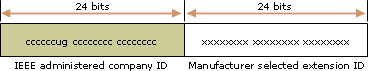
IEEE 802 addresses
網路介面卡的傳統介面識別元使用的 48 位元位址稱做 IEEE 802 位址。這個位址中包含一個 24 位元的公司 ID (又稱做製造商 ID) 和一個 24 位元的延伸識別元 (又稱做介面板識別元)。裡面有專門指派給每個網路介面卡及的公司 ID 以及組合時專門指派給每個網路介面卡的介面板識別元,形成全球唯一的 48 位元位址。這個 48 位元位址又稱做實體、硬體或媒體存取控制 (MAC) 位址。
IEEE 802 位址中定義了下列位元:
- 萬用/本機 (U/L)
U/L 位元是第一個位元組的第 7 個位元,可以決定這個位址是以萬用或本機方式管理。如果 U/L 位元設定為 0,表示 IEEE 是透過設計專用公司 ID 來管理這個位址。如果 U/L 位元設定為 1,表示是以本機方式來管理這個位址。網路系統管理員覆蓋了製造位址,並且指定了不同的位址。
- 個別/群組 (I/G)
I/G 位元是第一個位元組的低階位元,可以決定這個位址是個別位址 (單點傳送) 還是群組位址 (多點傳送)。如果設定為 0,表示這個位址是單點傳送位址。如果設定為 1,表示這個位址是多點傳送位址。
一般 802.x 網路介面卡位址的 U/L 及 I/G 位元都設定為 0,對應以萬用方式管理的單點傳送 MAC 位址。
(note: ICND COURSE UG/IL BITS IS WRONG)
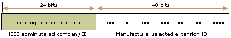
IEEE EUI-64 addresses
IEEE EUI-64 位址代表網路介面位址設定的新標準。公司 ID 的長度仍然是 24 個位元,但是延伸識別元是 40 個位元,為網路介面卡製造商建立較大的位址空間。EUI-64 位址使用與 IEEE 802 位址相同方式的 U/L 及 I/G 位元。
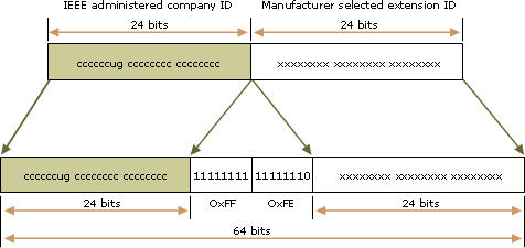
Mapping IEEE 802 addresses to EUI-64 addresses
若要根據 IEEE 802 位址來建立 EUI-64 位址,必須將 16 個位元的 11111111 11111110 (0xFFFE) 插入到公司 ID 及延伸識別元之間的 IEEE 802 位址中。下圖說明 IEEE 802 位址如何轉換到 EUI-64 位址。
Mapping EUI-64 addresses to IPv6 interface identifiers
若要取得 IPv6 單點傳送位址的 64 位元介面,必須在 EUI-64 位址中補充 U/L 位元 (若是 1,設定為 0;若是 0,設定為 1)。下圖說明如何轉換以萬用方式管理的單點傳送 EUI-64 位址。
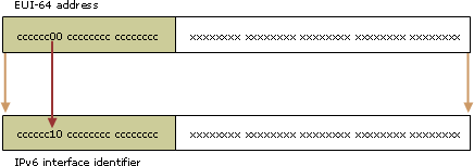
若要從 IEEE 802 位址取得 IPv6 介面識別元,您必須先將 IEEE 802 位址對應到 EUI-64 位址,再來補充 U/L 位元。下圖說明如何轉換以萬用方式管理的單點傳送 IEEE 802 位址。
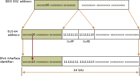
IEEE 802 address conversion example
主機有 Ethernet MAC 位址 00-AA-00-3F-2A-1C。首先,它在第 3 和第 4 個位元組之間插入 FF-FE,產生 00-AA-00-FF-FE-3F-2A-1C,轉換成 EUI-64 格式。接著,在第 1 個位元組中補充第 7 個位元 U/L。二進位格式的第 1 個位元組是 00000000。補充第 7 個位元後,就成為 00000010 (0x02)。最後的結果是 02-AA-00-FF-FE-3F-2A-1C,轉換成冒號十六進位表示法後就成為介面識別元 2AA:FF:FE3F:2A1C。最後,對應到網路介面卡 (搭配 MAC 位址 00-AA-00-3F-2A-1C) 的連結本機位址是 FE80::2AA:FF:FE3F:2A1C。
附註
- 補充 U/L 位元時,如果 EUI-64 位址是以萬用方式管理,請將 0x2 新增到第 1 個位元組。
Some unofficial notes on IPv6 prefixes and address
Updated: 2006-06-18
Created: 2003-12-18
Addressing information from many sources, like:
- IPv6 Bogon List.
- draft-ietf-ipv6-deprecate-site-local-02.
- IANA ipv6-tla-assignments
- RFC 2928
- RFC 2373
- RFC 2374
General note on unicast addresses: the first 16 bits are the TLA, the next 8 bits must be zero, then 24 bits of NLA (48 bits total), 16 bits of SLA (64 bits total), and 64 bits for the interface.
Also, there are issues on internet-wide routes and the length of prefixes. Someone has written some recommendations which illustrate what is expected to be routeable.
The table below is exhaustive.
|
IPv6 unicast and anycast address ranges |
||
|
Prefix |
Up to |
Notes |
|
0000::/8 |
00ff::/8 |
Reserved |
|
0000::0/128 |
0000::0/128 |
node local: unspecified address |
|
0000::1/128 |
0000::1/128 |
node local: localhost |
|
0000::0000:0000:0000/96 |
0000::0000:ffff:ffff/96 |
IPv4 compatible |
|
0000::ffff:0000:0000/96 |
0000::ffff:ffff:ffff/96 |
IPv4 mapped |
|
0100::/8 |
01ff::/8 |
unassigned |
|
0200::/7 |
03ff::/7 |
NSAP |
|
0400::/7 |
05ff::/7 |
IPX (obsolete) |
|
0600::/7 |
06ff::/7 |
unassigned |
|
0800::/5 |
0fff::/5 |
unassigned |
|
1000::/4 |
1fff::/4 |
unassigned |
|
2000::/3 |
3fff::/3 |
aggregatable global |
|
2000:0000::/16 |
2000:ffff::/16 |
reserved |
|
2001:0000:0000:/32 |
2001:0000:ffff:/32 |
Teredo, non Microsoft (official) |
|
2001:0001::/32 |
2001:ffff::/32 |
sub TLAs |
|
2001:0000::/23 |
2001:01ff::/23 |
sub TLAs: IANA |
|
2001:0200::/23 |
2001:03ff::/23 |
sub TLAs: APNIC |
|
2001:0400::/23 |
2001:04ff::/23 |
sub TLAs: ARIN |
|
2001:0600::/23 |
2001:07ff::/23 |
sub TLAs: RIPE NCC |
|
2001:0800::/23 |
2001:09ff::/23 |
sub TLAs: RIPE NCC |
|
2001:0a00::/23 |
2001:0bff::/23 |
sub TLAs: RIPE NCC |
|
2001:0c00::/23 |
2001:0dff::/23 |
sub TLAs: APNIC. Among these 2001:0db8::/32 is reserved for example addresses, and will not be allocated. |
|
2001:0e00::/23 |
2001:0fff::/23 |
sub TLAs: APNIC |
|
2001:1200::/23 |
2001:13ff::/23 |
sub TLAs: LACNIC |
|
2001:1400::/23 |
2001:15ff::/23 |
sub TLAs: RIPE NCC |
|
2001:1600::/23 |
2001:17ff::/23 |
sub TLAs: RIPE NCC |
|
2001:1800::/23 |
2001:19ff::/23 |
sub TLAs: ARIN |
|
2002:0000::/16 |
2002:ffff::/16 |
6to4 |
|
3ffe:0000::/16 |
3ffe:ffff::/16 |
6bone pseudo TLAs |
|
3ffe:831f:0000:/32 |
3ffe:831f:ffff:/32 |
Teredo, Microsoft (experimental) |
|
3fff:0000::/16 |
3fff:ffff::/16 |
reserved |
|
4000::/3 |
5fff::/3 |
unassigned |
|
6000::/3 |
7fff::/3 |
unassigned |
|
8000::/3 |
9fff::/3 |
unassigned |
|
a000::/3 |
bfff::/3 |
unassigned |
|
c000::/3 |
dfff::/3 |
unassigned |
|
e000::/4 |
efff::/4 |
unassigned |
|
f000::/5 |
f7ff::/5 |
unassigned |
|
f800::/6 |
f9ff::/6 |
unassigned |
|
fa00::/7 |
fbff::/7 |
unassigned |
|
fc00::/7 |
fdff::/7 |
|
|
fe00::/9 |
fe7f::/9 |
unassigned |
|
fe80::/9 |
feff::/9 |
local |
|
fe80:0000::/10 |
febf:0000::/10 |
link local |
|
fec0:0000::/10 |
feff:0000::/10 |
site local (deprecated) |
The multicast table below is exhaustive, except that any ranges not described in the fourth hex digit are reserved.
|
IPv6 multicast address ranges |
||
|
Prefix |
Up to |
Notes |
|
ff00::/8 |
ffff::/8 |
multicast |
|
ff00::/12 |
ff0f::/12 |
well known |
|
ff01::/16 |
ff01::/16 |
well known link local |
|
ff02::/16 |
ff02::/16 |
well known site local |
|
ff02:0:0:0:0:1:ff00::/104 |
ff02:0:0:0:0:1:ffff::/104 |
well known solicited-node |
|
ff05::/16 |
ff05::/16 |
well known site local |
|
ff08::/16 |
ff08::/16 |
well known organization local |
|
ff0e::/16 |
ff0e::/16 |
well known global |
|
ff10::/12 |
ff1f::/12 |
transient |
|
ff11::/16 |
ff11::/16 |
transient link local |
|
ff12::/16 |
ff12::/16 |
transient site local |
|
ff15::/16 |
ff15::/16 |
transient site local |
|
ff18::/16 |
ff18::/16 |
transient organization local |
|
ff1e::/16 |
ff1e::/16 |
transient global |
|
ff20::/12 |
ff2f::/12 |
unassigned |
|
ff30::/12 |
ff3f::/12 |
RFC 3306 prefix based multicast |
|
ff30:0000:0000:0000:0000:0000::/96 |
ff30:0000:0000:0000:0000:0000::/96 |
RFC 3306 source-specific multicast |
|
ff70::/12 |
ff7f::/12 |
RFC 3956 embedded-RP multicast |
|
ff40::/10 |
ffff::/10 |
unassigned |
Special interface numbers in anycast addresses.
|
IPv6 unicast/anycast interfaces |
|
|
Suffix |
Notes |
|
*:0000 |
Nearest router |
|
*:fff7:ffff:ffff:ff80-ffff |
Reserved anycast addresses (EUI-64) |
|
*:fff7:ffff:ffff:fffe |
Mobile IPv6 home-agents (EUI-64) |
|
*:ffff:ffff:ffff:ff80-ffff |
Reserved anycast addresses (non EUI-64) |
|
*:ffff:ffff:ffff:fffe |
Mobile IPv6 home-agents (non EUI-64) |
|
fe80::c171:3a50 |
Nearest 6to4 gateway (193.113.58.80) |
IPv6 multicast interfaces
Info from RFC 2375.
|
IPv6 multicast interfaces (group ids) |
|
|
Suffix |
Notes |
|
ff0?::0000 |
reserved |
|
ff0?::0100 |
VMTP Managers Group |
|
ff0?::0101 |
Network Time Protocol (NTP) |
|
ff0?::0102 |
SGI-Dogfight |
|
ff0?::0103 |
Rwhod |
|
ff0?::0104 |
VNP |
|
ff0?::0105 |
Artificial Horizons – Aviator |
|
ff0?::0106 |
NSS – Name Service Server |
|
ff0?::0107 |
AUDIONEWS – Audio News Multicast |
|
ff0?::0108 |
SUN NIS+ Information Service |
|
ff0?::0109 |
MTP Multicast Transport Protocol |
|
ff0?::010A |
IETF-1-LOW-AUDIO |
|
ff0?::010B |
IETF-1-AUDIO |
|
ff0?::010C |
IETF-1-VIDEO |
|
ff0?::010D |
IETF-2-LOW-AUDIO |
|
ff0?::010E |
IETF-2-AUDIO |
|
ff0?::010F |
IETF-2-VIDEO |
|
ff0?::0110 |
MUSIC-SERVICE |
|
ff0?::0111 |
SEANET-TELEMETRY |
|
ff0?::0112 |
SEANET-IMAGE |
|
ff0?::0113 |
MLOADD |
|
ff0?::0114 |
any private experiment |
|
ff0?::0115 |
DVMRP on MOSPF |
|
ff0?::0116 |
SVRLOC |
|
ff0?::0117 |
XINGTV |
|
ff0?::0118 |
microsoft-ds |
|
ff0?::0119 |
nbc-pro |
|
ff0?::011a |
nbc-pfn |
|
ff0?::011b |
lmsc-calren-1 |
|
ff0?::011c |
lmsc-calren-2 |
|
ff0?::011d |
lmsc-calren-3 |
|
ff0?::011e |
lmsc-calren-4 |
|
ff0?::011f |
ampr-info |
|
ff0?::0120 |
mtrace |
|
ff0?::0121 |
RSVP-encap-1 |
|
ff0?::0122 |
RSVP-encap-2 |
|
ff0?::0123 |
SVRLOC-DA |
|
ff0?::0124 |
rln-server |
|
ff0?::0125 |
proshare-mc |
|
ff0?::0126 |
dantz |
|
ff0?::0127 |
cisco-rp-announce |
|
ff0?::0128 |
cisco-rp-discovery |
|
ff0?::0129 |
gatekeeper |
|
ff0?::012a |
iberiagames |
|
ff0?::0201 |
“rwho" Group (BSD) (unofficial) |
|
ff0?::0202 |
SUN RPC PMAPPROC_CALLIT |
|
ff0?::0002:0000-7ffd |
Multimedia Conference Calls |
|
ff0?::0002:7ffe |
SAPv1 Announcements |
|
ff0?::0002:7fff |
SAPv0 Announcements (deprecated) |
|
ff0?::0002:8000-8fff |
SAP Dynamic Assignments |
|
ff02::0001 |
all nodes |
|
ff02::0002 |
all routers |
|
ff02::0004 |
DVRMP routers |
|
ff02::0005 |
OSPFUGP |
|
ff02::0006 |
OSPFIGP designated routers |
|
ff02::0007 |
ST routers |
|
ff02::0008 |
ST hosts |
|
ff02::0009 |
RIP routers |
|
ff02::000a |
EIGRP routers |
|
ff02::000b |
mobile agents |
|
ff02::000d |
PIM routers |
|
ff02::000e |
RSVP encapsulation |
|
ff02::0001:0001 |
Link name |
|
ff05::0002 |
all routers |
|
ff05::0001:0003 |
all DHCP servers |
|
ff05::0001:0004 |
all DHCP relays |
|
ff05::0001:1000-13ff |
service location |
Sh ip processes command
Aside
show processes Command
router#show processes
CPU utilization for five seconds: 0%/0%; one minute: 0%; five minutes: 0%
PID Q Ty PC Runtime(ms) Invoked uSecs Stacks TTY Process
1 C sp 602F3AF0 0 1627 0 2600/3000 0 Load Meter
2 L we 60C5BE00 4 136 29 5572/6000 0 CEF Scanner
3 L st 602D90F8 1676 837 2002 5740/6000 0 Check heaps
4 C we 602D08F8 0 1 0 5568/6000 0 Chunk Manager
5 C we 602DF0E8 0 1 0 5592/6000 0 Pool Manager
6 M st 60251E38 0 2 0 5560/6000 0 Timers
7 M we 600D4940 0 2 0 5568/6000 0 Serial Backgroun
8 M we 6034B718 0 1 0 2584/3000 0 OIR Handler
9 M we 603FA3C8 0 1 0 5612/6000 0 IPC Zone Manager
10 M we 603FA1A0 0 8124 0 5488/6000 0 IPC Periodic Tim
11 M we 603FA220 0 9 0 4884/6000 0 IPC Seat Manager
12 L we 60406818 124 2003 61 5300/6000 0 ARP Input
13 M we 60581638 0 1 0 5760/6000 0 HC Counter Timer
14 M we 605E3D00 0 2 0 5564/6000 0 DDR Timers
15 M we 605FC6B8 0 2 011568/12000 0 Dialer event
注釋
關鍵字 解釋
CPU utilization for five seconds CPU在最後5秒鐘的使用率
one minute CPU在最後1分鐘的使用率
five minutes CPU在最後5分鐘的使用率
PID程序號碼
Q 程序號碼優先順序和程序號碼的狀態:
K(沒有優先順序,程序號碼被殺了),
D(沒有優先順序,程序號碼癱了),
X(沒有優先順序, 程序號碼中斷了),
C(緊急優先順序),
H(高優先順序),
M(中優先順序),
L(低優先順序)
Ty Ty當前的處理狀態:
*(cpu正在處理),
E (程序號碼正在等待一個重要動作),
S (程序號碼休眠),
rd (程序號碼已經在運行),
we (程序號碼等待一個重要動作),
sa (程序號碼等待一個指定的絕對時間的產生),
si (程序號碼等待一個指定的時間間隔),
sp (程序號碼等待一個指定的週期性的時間間隔),
st (程序號碼等待一個時間終止),
hg (程序號碼縣置),
xx (程序號碼死亡.).
PC 當程序號碼持續放棄CPU時程式計數註冊器的內容. 這個地方寫的是記憶體的位址用以代表程序號碼開始執行寫一次佔用的CP值0代表正在運行
Runtime (ms) 使用CPU累計時間 (毫秒)
Invoked 程序號碼的建立起程序號碼運行在CPU的總時間
uSecs 每次程序號碼使用平均cpu時間 (毫秒級)
Stacks 堆疊空間使用狀況. 斜線右邊的數字(/)表示總的堆疊空間。 左邊的數字代表空間利用率的最低水準線.
TTY 控制台設備相關的程序號碼.0代表程序號碼不是被控制台和通訊器相關的主系統主控台
Process 程序號碼的名字.程序號碼的名字不需要是唯一的 (一個程序號碼的幾分拷貝可以同時是啟動狀態的). 但是程序號碼id號必須是唯一的。
如何監視nat流量+如何看CPU使用率+看DHCP流量+暫停EIGRP LEARNING NEIGHBOR + ROUTER自動重開機
一.監視NAT網路流量 :
show ip nat translation
二 . 監視cpu使用率
show process cpu
三 . 監視DHCP流量
show ip accounting
! (前題must 貼accounting 的規則在最多內部流量的端口)
四 . 停止router運行 eigrp 禁止該界面收送Hello封包 , 阻止形成鄰居關係 ,界面將不會再傳送EIGRP資訊
router eigrp AS編號
passive-interface serial 端口編號
開啟router運行 eigrp 啟動該界面收送Hello封包 ,形成緊居關係 ,界面將繼續再傳送路徑資訊
router eigrp AS編號
no passive-interface serial 端口編號
五 . router定時重開
router> enable
router# reload at hh:mm dd(1~31) MM(1~12)
CPU utilization for five seconds: 63%/50%; one minute: 58%; five minutes: 58%
PID Runtime(ms) Invoked uSecs 5Sec 1Min 5Min TTY Process
1 4976 54773 90 0.00% 0.00% 0.00% 0 Load Meter
2 3788 670 5653 1.71% 0.22% 0.15% 130 Virtual Exec
24 3592 632 5683 0.00% 0.04% 0.09% 131 Virtual Exec
25 101868424 30627416 3326 8.76% 9.04% 10.41% 0 IP Input
CPU utilization for five seconds: 63%/50%
50%是指由於Interrupt switching 導致的CPU utilization, 所謂的Interrupt switching 也就是指所有除了process switching 的交換方式,例如fast switching, optimum switching, cef switching….所產生的CPU負載
Average utilization due to interrupts, during last five seconds
63%指的是最近5秒的CPU utilization總和,包括(interrupts + processes)
Average total utilization during last five seconds (interrupts + processes)
用63%-50%=13%, 這13%是基本由於process switching導致的CPU消耗,理解Cisco 路由器交換方式的人都知道,有一些流量路由器是必須使用process switching,例如icmp,也就ping, snmp等都是必須使用process switching
通常看來,如果打開了cef switching但是process switching部分的cpu utilization(63%-50%=13%)非常高,很可能目前情況不太正常,,因為如果打開cef的話,基本上除了icmp, snmp等類型的包外,都應該採用cef switching,但這部分差值由誰導致的,就要看show process cpu了, 從上面的例子可以看出來:
PID Runtime(ms) Invoked uSecs 5Sec 1Min 5Min TTY Process
25 101868424 30627416 3326 8.76% 9.04% 10.41% 0 IP Input
由於此路由器已經打開了cef,但為什麼還有這麼多的IP Input流量是通過process switching處理呢?
使用show interface state可以看到每個介面不同swiching方式產生的流量,如果某個介面的process部分很高,那很可能問題就出在這個埠。
Router#show interfaces stat
FastEthernet0/0
Switching path Pkts In Chars In Pkts Out Chars Out
Processor
7995038
553590227
8470311
629922225
Route cache
42017034 3042361084 47856422 3952941601
Total
50012072 3595951311 56326733 287896530
FastEthernet1/0
Switching path Pkts In Chars In Pkts Out Chars Out
Processor 1478297 178528355 1007368 101120880
Route cache 46470310 3666895196 40629605 2756450367
Total 47948607 3845423551 41636973 2857571247
使用show ip traffic命令來確認到底是那一種流量過大。
從下例中可以看出, 幾個不太正常的地:
1.在ICMP中有321413 unreachable,2263321 echo reply,很明顯路由器回應的ICMP太多了,如果每隔幾秒都有數量增加,建議在介面狀態下關掉IMCP redirects, unreachable以及echo reply,這些只會增加CPU負擔。
interface xxxx
no ip redirects
no ip unreachables
2.在UDP statistics中:
Rcvd: 7112 total, 0 checksum errors, 21093 no port
大量的no port就不太正常了,一般都是由於某些hacker軟體掃描埠造成的, 如果每隔幾秒都有數量增加,建議關掉proxy-arp
interface xxx
no ip proxy-arp
3. 在IP statistics,有89518 bad hop count,這一般是由於TTL過期導致的,如果每隔幾秒都有大量計數增加,很明顯,網路中存在routing loop,儘快檢查你的資料配置
或是詢問你的ISP怎麼給你做的路由。
Router#show ip traffic
IP statistics:
Rcvd: 190022549 total, 13327 local destination
2 format errors, 0 checksum errors, 89518 bad hop count
0 unknown protocol, 0 not a gateway
0 security failures, 0 bad options, 0 with options
Opts: 0 end, 0 nop, 0 basic security, 0 loose source route
0 timestamp, 0 extended security, 0 record route
0 stream ID, 0 strict source route, 0 alert, 0 cipso, 0 ump
0 other
Frags: 0 reassembled, 0 timeouts, 0 couldn’t reassemble
6583 fragmented, 0 couldn’t fragment
Bcast: 2433 received, 77 sent
Mcast: 0 received, 0 sent
Sent: 100452 generated, 99773529 forwarded
Drop: 430 encapsulation failed, 1479 unresolved, 0 no adjacency
3606 no route, 0 unicast RPF, 0 forced drop
ICMP statistics:
Rcvd: 0 format errors, 0 checksum errors, 0 redirects, 321413 unreachable
2281 echo, 0 echo reply, 0 mask requests, 0 mask replies, 0 quench
0 parameter, 0 timestamp, 0 info request, 0 other
0 irdp solicitations, 0 irdp advertisements
Sent: 0 redirects, 4 unreachable, 0 echo, 2263321 echo reply
0 mask requests, 0 mask replies, 0 quench, 0 timestamp
0 info reply, 89517 time exceeded, 0 parameter problem
0 irdp solicitations, 0 irdp advertisements
UDP statistics:
Rcvd: 7112 total, 0 checksum errors, 21093 no port
Sent: 5883 total, 0 forwarded broadcasts
TCP statistics:
Rcvd: 3935 total, 0 checksum errors, 4 no port
Sent: 2788 total
IPv6 tunnel over IPv4
Aside
IPV4 HEADER FIELD
0 1 2 3
0 1 2 3 4 5 6 7 8 9 0 1 2 3 4 5 6 7 8 9 0 1 2 3 4 5 6 7 8 9 0 1
+-+-+-+-+-+-+-+-+-+-+-+-+-+-+-+-+-+-+-+-+-+-+-+-+-+-+-+-+-+-+-+-+
|Version| IHL |Type of Service| Total Length |
+-+-+-+-+-+-+-+-+-+-+-+-+-+-+-+-+-+-+-+-+-+-+-+-+-+-+-+-+-+-+-+-+
| Identification |Flags| Fragment Offset |
+-+-+-+-+-+-+-+-+-+-+-+-+-+-+-+-+-+-+-+-+-+-+-+-+-+-+-+-+-+-+-+-+
| Time to Live |
Protocol 41
| Header Checksum |
+-+-+-+-+-+-+-+-+-+-+-+-+-+-+-+-+-+-+-+-+-+-+-+-+-+-+-+-+-+-+-+-+
| Source Address |
+-+-+-+-+-+-+-+-+-+-+-+-+-+-+-+-+-+-+-+-+-+-+-+-+-+-+-+-+-+-+-+-+
| Destination Address |
+-+-+-+-+-+-+-+-+-+-+-+-+-+-+-+-+-+-+-+-+-+-+-+-+-+-+-+-+-+-+-+-+
| Options | Padding |
+-+-+-+-+-+-+-+-+-+-+-+-+-+-+-+-+-+-+-+-+-+-+-+-+-+-+-+-+-+-+-+-+
| IPv6 header and payload …
/
+——-+——-+——-+——-+——-+——+——+
Source: RFC 3056, Connection of IPv6 Domains via IPv4 Clouds
IPv6 over IPV4 TUNNEL
IPV6 REF01
Aside
[IPV6 Intrduction]
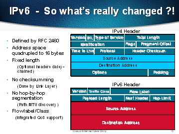
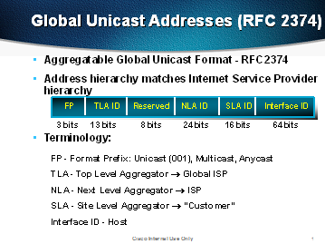
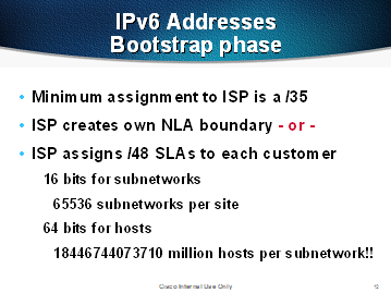
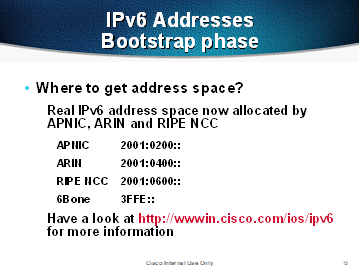
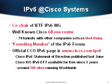
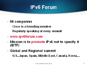
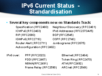
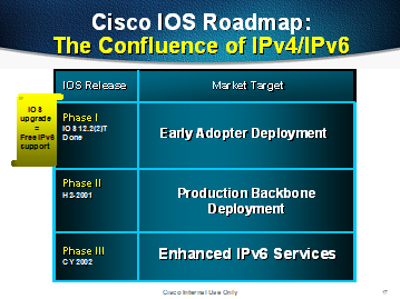
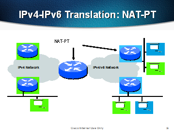
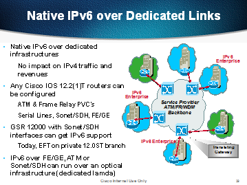
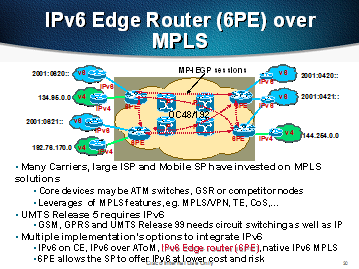
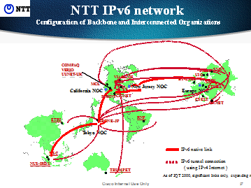
初識CAPWAP
Aside
初識CAPWAP
CAPWAP簡介
CAPWAP——Control And Provisioning of Wireless WLC Acess Points Protocol Specification。
其協定由兩個部分組成:
1. CAPWAP協定和 2.無線BINDING協定。
前者是一個通用的隧道協議,完成AP發現WLC等基本協議功能,和具體的無
線接入技術無關。
後者是提供具體和某個無線接入技術相關的配置管理功能。
這麼說吧,前者規定了各個階段需要幹什麼事,後者就是具體到在各種接入方式下應該怎麼完成這些事。
CAPWAP協議在2009年4月的RFC5415中發佈,無線BINGDING協議目前只出臺了接入方式為802.11的RFC,也是2009年4月發佈的,RFC編號為5416。
PS:離開主題一下,順帶提一下802.11、802.15、802.16、802.20等無線接入方式的區別。
*********************************************************************
目前,IEEE802旗下的無線網路通訊協定一共有
802.11、
802.15、
802.16
802.20
等四大種類,這四大類協定中又包含各種不同性能的子協定,顯得很混亂的樣子……
IEEE802.11體系定義的是無線局域網標準(WLAN,Wireless Local Area Network),針對家庭和企業中的局域網而設計,應用範圍一般局限在一個建築物或一個小建築物群(如學校、社區等)。
IEEE802.15定義的其實是無線個人網路(WPAN,Wireless Personal Area Network),主要用於個人電子設備與PC的自動互聯,這類設備包括手機、MP3播放機、便攜媒體播放機、數碼相機、掌上型電腦等等。
IEEE802.16是一種寬頻無線接入技術(Broadband Wireless WLCcess,BWA),主要用於遠距離、高速度的通訊環境,定義的是都會區網路絡(MAN,Metropolitan Area Network),性能可媲美Cable電纜、DSL、T1專線等傳統的有線技術。IEEE802.16包含802.16和802.16a兩項子協議,前者的作用距離為2公里,傳輸速率在30Mbps至130Mbps之間,而802.16a的傳輸距離可達到50公里,速率也能達到75Mbps—看得出,在上述各種無線通訊技術中,還沒有哪項技術可以在有效範圍和性能標準上都蓋過IEEE802.16a。
IEEE802.20與802.16在特性上有些類似,都具有傳輸距離遠、速度快的特點。不過802.20是一項移動寬頻接入技術(Mobile Broadband Wireless WLCcess,MBWR),他更側重於設備的可移動性,例如在高速行駛的火車、汽車上都能實現資料通訊(802.16無法做到這一點)。
*********************************************************************
CAPWAP協議的主要功能:
AP自動發現WLC,
WLC對AP進行安全認證,
AP從WLC獲取軟體映射,
AP從WLC獲得初始和動態配置等。
此外,系統可以支援本地資料轉發和集中資料轉發。
Lightweight AP架構讓WLC具有了對整個WLAN網路的完整視圖,為無線漫遊、無線資源管理等業務功能的實現提供了基礎。
2一些名詞
無線控制器(WLC/AC):網路實體,在網路架構的資料層,控制層,管理層或者聯合起來提供AP到網路的訪問服務。
CAPWAP控制通道:一個雙向通道,由WLC的IP位址,AP的IP位址,WLC控制埠,AP控制埠,傳輸層協議(UDP或者UDP-Lite)定義,在這之上可以收發CAPWAP的控制資訊。
CAPWAP資料通道:一個雙向通道,由WLC的IP位址,AP的IP位址,WLC資料埠,AP資料埠,傳輸層協定(UDP或者UDP-Lite)定義,在這之上可以收發CAPWAP的資料包文。
STATION(Client):一個包含無線介面的設備
無線終端AP:物理或者網路實體,包含一個射頻天線和無線實體層可
傳輸和接收 STA在無線存取網路的資料。
3 CAPWAP的模式
CAPWAP協定支援兩種模式的操作:Split MAC和Local MAC。
Split MAC:在split MAC模式下,所有二層的無線資料和管理訊框都會被
CAPWAP協定封裝,然後在WLC和(AP/WTP)之間交換。
如下圖中所示,從一個Station收到的無線訊框,會被直接封裝,然後轉發給
WLC。
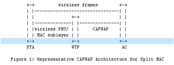
Local MAC:本地轉發模式允許資料訊框可以用本地橋或者使用802.3的訊框形式用隧道轉發。
在這種情況下,二層無線管理訊框在AP本地已經處理,然後轉發給WLC。
下圖顯示了本地轉發模式,Station傳送的無線訊框被封裝成802.3資料訊框,然後轉發給WLC。

2.4 CAPWAP的資料類型
CAPWAP協定傳輸層運輸兩種類型的資料:
資料消息
封裝轉發無線訊框
控制消息
管理AP和WLC之間交換的管理消息
CAPWAP資料和控制資訊基於不同的UDP埠發送,且允許被分割,因此資料和控制資訊可以超過MTU長度。
2.5 CAPWAP會話創建過程
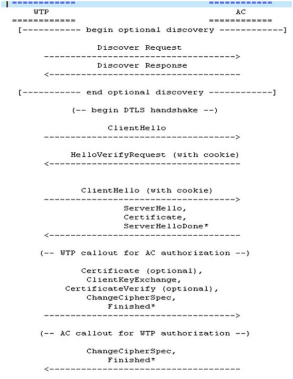
CAPWAP協議從發現階段開始。APs發送一個發現請求消息,任何接收到這個請求的WLC將會回應一個發現回應資訊。接收到發現響應資訊,AP選擇一個WLC來建立一個 基於DTLS的安全會話。為了建立DTLS安全連接,AP將需要一個預先提供的資料,將在後面說明。CAPWAP協定資訊將會被分段成網路支援的最大長度。
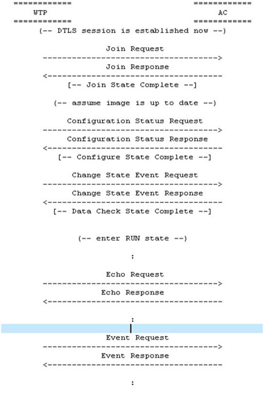
一旦AP和WLC完成了DTLS會話建立,兩者之間會交換配置,來在版本資訊上達成一致。在這個交換過程之間,AP可能會接收到規定設置,然後會開啟這些設置。
當AP和WLC之間完成版本和設置的交換,並且AP已經開啟,CAPWAP協議將被使用來封裝WLC和AP之間發送的無線資料訊框。如果使用者資料或者協定控制資料長度超過 AP和WLC之間的MTU會導致CAPWAP協定將L2層訊框分片。被分片的CAPWAP資訊將會被重新組成原來的封裝資訊。
2.5.1 WLC發現機制
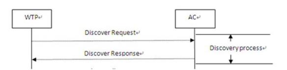
AP使用WLC發現機制來得知哪些WLC是可用的,決定最佳的WLC來建立CAPWAP連接。
AP的發現過程是可選的。如果在AP上靜態配置了WLC,那麼AP並不需要完成WLC的發現過程。
AP首先發送一個 Discovery Request message給受限的廣播位址,或者CAPWAP的多播地址(224.0.1.140),或者是預配置的WLC的單播地址。在IPV6網路中,由於廣播並不存在,因此使用"All WLCs multicast address" (FF0X:0:0:0:0: 0:0:18C)來代替。
當接收到Discovery Request message消息,WLC發送一個單播Discovery Response message給AP。
AP可以通過Discovery Response message中所帶的WLC優先順序,支持的CAPWAP binding來選擇與哪個WLC建立會話。
除了上面的發現機制,AP還可以使用DNS或者DHCP來發現WLC。
2.5.2 DTLS握手
AP首先發送一個ClientHello消息來發起握手,說明它支援的密碼演算法清單、壓縮方法及最高協定版本和其他一些需要的消息。
WLC回復一個HelloVerifyReuqest 消息,client必須重傳添加了cookie的ClientHello。server然後驗證cookie,如果有效的話才開始進行握手。
WLC回應一個ServerHello消息,包含伺服器選擇的連接參數,源自用戶端初期所提供的ClientHello,確定了這次通信所需要的演算法,然後發過去自己的證書(裡面包含了身份和自己的公開金鑰)。
Client在收到這個消息後會生成一個秘密消息,用SSL伺服器的公開金鑰加密後傳過去,SSL伺服器端用自己的私密金鑰解密後,工作階段金鑰協商成功,雙方可以用同一份工作階段金鑰來通信了。
2.5.3 DTLS認證和授權
DTLS支援終端認證方式為:證書(certificate)和預共用金鑰(pre-shared key)。
CAPWAP認證中使用證書支援的演算法是
TLS_RSA_WITH_AES_128_CBC_SHA [RFC5246](MUST SUPPORT)
TLS_DHE_RSA_WITH_AES_128_CBC_SHA [RFC5246](SHOULD SUPPORT)
TLS_RSA_WITH_AES_256_CBC_SHA [RFC5246](MAY SUPPORT)
TLS_DHE_RSA_WITH_AES_256_CBC_SHA [RFC5246] ](MAY SUPPORT)
在RFC4279中定義了多種預共用金鑰的認證方式,CAPWAP中主要關心下面兩種:
Pre-Shared Key (PSK) key exchange algorithm
DHE_PSK key exchange algorithm
同樣,CAPWAP定義了預共用金鑰支援的演算法
TLS_PSK_WITH_AES_128_CBC_SHA [RFC5246] (MUST SUPPORT)
TLS_DHE_PSK_WITH_AES_128_CBC_SHA [RFC5246] (MUST SUPPORT)
TLS_PSK_WITH_AES_256_CBC_SHA [RFC5246] ](MAY SUPPORT)
TLS_DHE_PSK_WITH_AES_256_CBC_SHA [RFC5246] ](MAY SUPPORT)
2.5.4 CAPWAP狀態機
CAPWAP狀態機,是被WLC和AP同時使用的。對於每個定義的狀態,只有特定的消息才被允許收發。
因為AP只會和單個WLC通訊,因此只會有一個CAPWAP的狀態機。而WLC與AP有很大差別,因為WLC同時和許多AP通訊。
DTLS和CAPWAP的狀態機由命令和通告的API介面聯繫起來。
DTLS狀態機的變遷由CAPWAP狀態機的命令觸發。
CAPWAP狀態機的變遷由DTLS狀態機的通告觸發
CAPWAP狀態機:
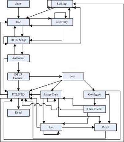
2.5.4.1 CAPWAP to DTLS Commands
DTLSStart
開啟DTLS會話的建立
DTLSListen
監聽DTLS會話請求
DTLSWLCcept
允許DTLS會話建立
DTLSAbortSession
導致正在進行中的DTLS會話的中斷
DTLSShutdown
關閉DTLS會話
DTLSMtuUpdate
改變DTLS模組的MTU設定大小。預設大小為1468位元組
2.5.4.2 DTLS to CAPWAP Notifications
DTLSPeerAuthorize
DTLS會話建立過程中,通知CAPWAP模組來認證會話。
DTLSEstablished
通知CAPWAP模組DTLS會話已經成功建立
DTLSEstablishFail
DTLS會話建立失敗
DTLSAuthenticateFail
DTLS會話建立過程由於認證失敗而終止。
DTLSAborted
通知CAPWAP模組它要求的DTLS會話建立過程已經終
DTLSReassemblyFailure
通知CAPWAP模組DTLS分片組裝失敗
DTLSDecapFailure
通知CAPWAP模組發生了一個解碼錯誤
DTLSPeerDisconnect
通知CAPWAP模組DTLS會話已經關閉
2.5.5 WLC執行緒
WLC使用了三個"執行緒"(thread)的概念。
監聽執行緒:
通過DTLSlisten命令,WLC監聽執行緒DTLS會話建立請求。創建的時候,監聽執行緒開啟DTLS Setup狀態。當狀態機進入Authorize狀態,且DTLS會話生效之後,監聽執行緒創建一個指定的AP指定會話服務執行緒和狀態空間。
發現執行緒:
WLC的發現執行緒負責接收和回應發現請求消息。
服務執行緒:
WLC的服務進程處理每個AP的狀態和每個AP連接的執行緒。這個執行緒在認證後被監聽執行緒創建。一旦創建,服務執行緒會繼承監聽執行緒的一份狀態機空間的拷貝。當與AP之間的通訊完成後,服務執行緒關閉,所有的資源都會被釋放。
注意,在這裡使用了執行緒這個術語,但是並不代表實現者就必須使用執行緒。這只是一個實現WLC狀態機的可用的方法
2.5.6 CAPWAP狀態機詳解
2.5.6.1 Start to Idle
這個狀態變遷發生在設備初始化完成。
AP: 開啟CAPWAP狀態機。
WLC: 開啟CAPWAP狀態機。
2.5.6.2 Idle to Discovery
這個狀態變遷發生是為了支援CAPWAP發現進程。
AP:
AP進入發現狀態是為了優先去傳輸第一個Discovery Request message。在進入這個狀態之前,AP設置發現DiscoveryInterval timer,將DiscoveryCount counter為0.同時清理以前的發現過程中可能會從WLC收到的所有資訊。
WLC:
由發現執行緒執行,且發生在收到一個發現請求資訊的時候。此時,WLC需要給這個資訊回應一個Discovery Response message 。
2.5.6.3 Discovery to Discovery
在這個發現狀態,AP決定連接哪個WLC。
AP:
這個狀態變遷發生在發現DiscoveryInterval timer觸發的時候。對於這個事件的每次變遷,DiscoveryCount counter會遞增。一旦AP發送了Discovery Request message,AP重啟DiscoveryInterval timer。
WLC:
對於WLC來說,這個狀態變遷是無效的。
2.5.6.4 Discovery to Idle
當發現過程完畢的時候,WLC的發現執行緒將會觸發這個變遷。
AP:
對於AP來說,這個狀態變遷是無效的。
WLC:
這個狀態變遷由WLC發現執行緒執行,當發現執行緒傳輸了一個給Discovery Request回送了一個Discovery Response的時候,就會觸發這個過程。
2.5.6.5 Discovery to Sulking
當AP發現WLC失敗的時候會觸發這個狀態變遷。
AP:
發生在DiscoveryInterval timer超時的時候。 且此時DiscoveryCount變數等於MaxDiscoveries 。在進入這個狀態之前,AP必須開啟SilentInterval timer 。當在Sulking狀態的時候,所有收到的CAPWAP協定資訊都會被忽略。
WLC:
對於WLC來說,這個狀態變遷是無效的。
2.5.6.6 Sulking to Idle
這個狀態變遷發生在AP需要重新開機發現過程的時候。
AP:
當SilentInterval timer觸發,AP進入到這個狀態。FailedDTLSSessionCount, DiscoveryCount和FailedDTLSAuthFailCount計數器被清零。
WLC:
對於WLC來說,這是一個無效的狀態變遷。
2.5.6.7 Sulking to Sulking
sulking狀態提供安靜時段,最小化DOS攻擊的危險。
AP:
在sulking狀態收到的所有來自WLC得資訊都會被忽略。
WLC:
對於WLC來說,這是一個無效的狀態變遷
2.5.6.8 Idle to DTLS Setup
這個狀態變遷發生在跟對端建立安全的DTLS會話的時候。
AP:
AP通過調用DTLSStart命令來初始化這個狀態變遷,開始與選定WLC進行DTLS會話,且開啟WaitDTLS timer。此時,忽略了發現過程,假設AP有本地配置的WLC。
WLC:
從start狀態進入Idle狀態,監聽執行緒自動變遷至DTLS Setup狀態,調用DTLSListen命令,並且開啟WaitDTLS timer。
2.5.6.9 Discovery to DTLS Setup
AP:
AP調用DTLSStart命令來初始化這個變遷,開始與指定WLC建立DTLS會話。
WLC:
對於WLC來說,這是一個無效的狀態變遷。
2.5.6.10 DTLS Setup to Idle
當DTLS連接失敗的時候發生這個狀態變遷。
AP:
此時AP接收到DTLSEstablishFail通知,並且FailedDTLSSessionCount或者FailedDTLSAuthFailCount counter 沒有達到MaxFailedDTLSSessionRetry值。這個錯誤通知終止了DTLS會話的建立。當接收到這個通知,FailedDTLSSessionCount計時器會遞增。
這個狀態變遷也會發生在WaitDTLS timer超時的情況下。
WLC:
對於WLC來說,這是一個無效的狀態變遷。
2.5.6.11 DTLS Setup to Sulking
當重複嘗試建立DTLS連接失敗的時候,會發生此狀態變遷。
AP:
當FailedDTLSSessionCount或者FailedDTLSAuthFailCount到達最大值MaxFailedDTLSSessionRetry的時候,AP進入此狀態變遷。進入這個狀態,AP必須開啟SilentInterval計時器,且所有接收到的CAPWAP和DTLS協議資訊將會被忽略。
WLC:
對於WLC來說,這是一個無效的狀態變遷。
2.5.6.12 DTLS Setup to DTLS Setup
當DTLS會話建立失敗的時候會發生這個狀態變遷。
AP:
對於AP來說,這是一個無效的狀態變遷
WLC:
當接收到一個來自DTLS的DTLSEstablishFail通知,WLC監聽執行緒初始化這個狀態變遷。當收到這個通告,FailedDTLSSession Count會遞增,監聽執行緒然後調用DTLSListen命令。
2.5.6.13 DTLS Setup to Authorize
這個狀態變遷發生在當一個正在建立DTLS會話需要認證才能繼續進行的時候。
AP:
當AP接收到DTLSPeerAuthorize通告的時候,開始這個狀態變遷。在進入這個狀態之前,AP對WLC的證書執行一個認證檢查。
WLC:
當DTLS模組初始化DTLSPeerAuthorize通告的時候,WLC監聽執行緒這個狀態變遷。監聽執行緒fork一個服務執行緒和一個狀態機內容的拷貝,然後,服務執行緒會對AP證書執行認證。
2.5.6.14 Authorize to DTLS Setup
當監聽執行緒對新進入的會話開始監聽的時候,發生這個狀態變遷。
AP:
對於AP來說,這是個無效的狀態變遷
WLC:
當WLC監聽執行緒創建AP內容空間和服務執行緒後,發生這個狀態變遷。監聽執行緒然後調用DTLSListen命令。
2.5.6.15 Authorize to DTLS Connect
當通知DTLS棧會話將要建立的時候發生這個狀態變遷。
AP:
當WLC證書被AP認證成功的時候,會發生這個狀態變遷。調用DTLSWLCcept命令來完成。
WLC:
當AP證書成功通過WLC認證的時候發生這個狀態變遷。調用DTLSWLCcept來完成。
2.5.6.16 DTLS Connect to DTLS Teardown
當DTLS會話建立失敗的時候發生。
AP:
當AP接收到一個DTLSAborted或者DTLSAuthenticateFail通告,告知這個DTLS會話建立不成功的時候,發生這個狀態變遷。當因為DTLSAuthenticateFail通告發生的狀態變遷,FailedDTLSAuthFailCount會增加,否則,FailedDTLSSessionCount計數器增加。這個狀態變遷也在WaitDTLS 計時器超時的時候發生,此時AP開啟DTLSSessionDelete計時器。
WLC:
當AP接收到一個DTLSAborted或者DTLSAuthenticateFail通告,告知這個DTLS會話建立不成功,此時FailedDTLSAuthFailCount和FailedDTLSSessionCount 不等於MaxFailedDTLSSessionRetry的時候,發生這個狀態變遷。 這個狀態變遷也在WaitDTLS計時器超時的時候發生。
2.5.6.17 DTLS Connect to Join
當會話成功建立的時候發生。
AP:
當AP接收到一個DTLSEstablished通告,表明這個DTLS會話成功建立的時候,發生這個狀態變遷。當接收到這個通告FailedDTLSSessionCount計時器被設置為0.AP進入join狀態,傳輸Join Request給WLC。AP停止WaitDTLS計時器。
WLC:
當WLC接收到DTLSEstablished通告,表明這個DTLS會話成功建立的時候,發生這個狀態變遷。當接收到這個通告,FailedDTLSSessionCount計時器被設置為0.WLC停止WaitDTLS計時器,開啟WaitJoin計時器。
2.5.6.18 Join to DTLS Teardown
當Join過程失敗的時候發生。
AP:
當AP接收到一個帶有錯誤代碼消息單元的Join回應訊息,或者在Join回應中由WLC提供的Image與AP現在運行的版本不一樣,且AP的non-volatile memory中有這個請求的版本號.這個導致AP初始化DTLSShutdown命令。當AP接收到下面任何一個通告的時候,也會發生這個過程:DTLSAborted, DTLSReassemblyFailure, or DTLSPeerDisconnect.AP開啟DTLSSessionDelete 計時器。
WLC:
發生在WaitJoin超時或者WLC傳送了一個帶有錯誤碼的Join Response的時候。WLC初始化DTLSShutdown命令。當WLC收到下面任何一個DTLS通告的時候,也會發生這個過程:DTLSAborted, DTLSReassemblyFailure, DTLSPeerDisconnect。 此時,WLC開啟DTLSSessionDelete計時器。
2.5.6.19 Join to Image Data
AP和WLC下載可執行的firmware時使用這個狀態變遷。
AP:
當AP收到了一個成功的Join Response message,告知它當前運行的版本與要求的不一樣的時候,發生這個狀態變遷。且此時,AP的non-volatile storage中也沒有要求的image版本。AP初始化EchoInterval計時器。
WLC:
當WLC發送一個Join Response給AP之後,從AP接受到一個Image Data Request資訊,發生這個狀態變遷。WLC停止WaitJoin計時器,發送一個Image Data Response message給AP。
2.5.6.20 Join to Configure
AP和WLC使用這個狀態變遷來交換配置資訊。
AP:
當AP收到了一個successful Join Response message,且此時當前運行的版本與要求的一致。AP發送一個Configuration Status Request message給WLC,消息中包含了當前配置資訊。
WLC:
當從AP接收到Configuration Status Request message,且消息中包含指定消息元素需要覆蓋AP的配置。WLC停止WaitJoin計時器,發送Configuration Status Response message,並且開啟ChangeStatePendingTimer計時器。
2.5.6.21 Configure to Reset
這個狀態變遷被用來重啟連接。這個可能被配置階段發生的錯誤導致,或者是AP決定它有需要來重啟讓新的配置生效。CAPWAP Reset命令用來告訴對端它將會初始化一個DTLSteardown。
AP:
AP接收到Configuration Status Response message告訴它有錯誤發生或者覺得有需要重新讓新配置生效的時候,AP進入reset 狀態。
WLC:
WLC接收到一個來自AP的Change State Event message,當這個消息包含了因為WLC的策略而不允許AP提供服務的錯誤的時候,WLC變遷到reset狀態。這個狀態變遷也會在ChangeStatePendingTimer計時器超時的時候發生。
2.5.6.22 Authorize to DTLS Teardown
這個狀態變遷為了通知DTLS會話將要終止。
AP:
當AP認證失敗的時候,發生這個狀態變遷。AP然後調用DTLSAbortSession命令終止這個DTLS會話。這個狀態變遷也會發生在WaitDTLS計時器超時的情況下。AP開啟DTLSSessionDelete計時器。
WLC:
這個狀態變遷發生在WLC認證失敗的時候。WLC調用DTLSAbortSession命令終止DTLS會話。這個狀態變遷也會發生在WaitDTLS計時器超時的時候。WLC開啟DTLSSessionDelete計時器。
2.5.6.23 Configure to DTLS Teardown
這個變遷發生在因為DTLS錯誤導致的配置過程終止的時候。
AP:
當接收到下列任一DTLS通告:DTLSAborted,DTLSReassemblyFailure, 或者 DTLSPeerDisconnect,AP進入這個狀態。如果它接收到頻繁的DTLSDecapFailure通告,AP也有可能會終止DTLS會話。此時,AP開啟DTLSSessionDelete計時器。
WLC:
當接收到下列任一DTLS通告:DTLSAborted,DTLSReassemblyFailure,或者DTLSPeerDisconnect,WLC進入這個狀態。如果它接收到頻繁的DTLSDecapFailure通告,AP也有可能會終止DTLS會話。WLC開啟DTLSSessionDelete計時器。
2.5.6.24 Image Data to Image Data
image資料狀態在AP和WLC在firmware下載階段的時候使用。
AP:
當AP接收到一個表明WLC有更多資料要發送的Image Data Response message的時候,AP進入Image Data state。
AP 接收到頻繁的Image Data Requests,此時,它將會重新設置ImageDataStartTimer的時間來保證它接收到下一個來自WLC的Image Data Request。
AP的EchoInterval 超時的時候,這會導致AP傳輸一個Echo Request message,並且重新設置它的EchoInterval計時器。
AP接收到一個來自WLC的Echo Response。
WLC:
當WLC在Image資料狀態下接收到來自AP的Image Data Response message。
當WLC接收到一個來自AP的Echo Request。這個會導致WLC用一個Echo Response來進行回應,然後重新設置EchoInterval計時器。
2.5.6.25 Image Data to Reset
AP下載image後重啟,重新設置DTLS連接
AP:
當image的下載完成,或者ImageDataStartTimer計時器超時,AP進入reset狀態。
接收到一個來自WLC的Image Data Response message消息的時候轉入這個狀態。
WLC:
當image傳輸成功完成,或者在傳輸過程中發生了一個錯誤的時候,WLC進入reset狀態。
2.5.6.26 Image Data to DTLS Teardown
當firmware下載過程由於DTLS錯誤而終止時發生
AP:
接收到下麵任一DTLS通告:DTLSAborted,DTLSReassemblyFailure,或者DTLSPeerDisconnect的時候
收到頻繁的DTLSDecapFailure通告的時候關閉DTLS會話。
此時AP開啟DTLSSessionDelete計時器。
WLC:
當WLC接收到下麵任一DTLS通告:DTLSAborted,DTLSReassemblyFailure,或者DTLSPeerDisconnect的時候
收到頻繁的DTLSDecapFailure通告的時候關閉DTLS會話。
此時WLC開啟DTLSSessionDelete計時器。
2.5.6.27 Configure to Data Check
當AP與WLC確認配置資訊的時候
AP:
從WLC接收到一個成功的Configuration Status Response message的時候,AP轉入Data Check狀態。此時AP發送一個Change State Event Request message。
WLC:
當WLC接收到來自AP的Change State Event Request message時發生。然後,WLC回應一個Change State Event Response message。此時, WLC必須開啟DatWLCheckTimer計時器,關閉ChangeStatePendingTimer計時器。
2.5.6.28 Data Check to DTLS Teardown
當AP沒有完成Data Check 交互的時候。
AP:
當CAPWAP重傳計時器超時,AP仍沒有接收到Change State Event Response message。
當RetransmitCount達到MaxRetransmit的時候。
此時,AP開啟DTLSSessionDelete計時器。
WLC:
當DatWLCheckTimer計時器超時的時候進入這個狀態。
此時,WLC開啟DTLSSessionDelete計時器。
2.5.6.29 Data Check to Run
當控制和資料通道建立的時候
AP:
條件:當接收到來自WLC的成功Change State Event Response message。
動作:AP初始化一個資料通道,這個資料通道可選擇是否由DTLS加密。開啟DatWLChannelKeepAlive計時器,發送一個Data Channel Keep-Alive資訊。然後,AP開啟EchoInterval計時器和DatWLChannelDeadInterval計時器。
WLC:
條件:當WLC接收到Data Channel Keep-Alive資訊,資訊中的session Id與AP在Join Request中設定的一致。
動作:WLC關閉DatWLCheckTimer計時器。注意,如果WLC要求資料通道要加密,那麼將會建立一個資料通道的DTLS會話。在接收到Data Channel Keep-Alive資訊之前,WLC就會發送一個自己的Data Channel Keep-Alive資訊。
2.5.6.30 Run to DTLS Teardown
當DTLS發生錯誤的時候
AP:
條件:
接收到下面任何一個DTLS通告:DTLSAborted,DTLSReassemblyFailure, 或者DTLSPeerDisconnect。
接收到頻繁的DTLSDecapFailure通告。
RetransmitCount達到MaxRetransmit值。
動作:
開啟DTLSSessionDelete計時器。
WLC:
條件:
接收到下面任何一個DTLS通告:DTLSAborted,DTLSReassemblyFailure, 或者DTLSPeerDisconnect。
接收到頻繁的DTLSDecapFailure通告。
RetransmitCount達到MaxRetransmit值。
EchoInterval計時器觸發。
動作:
開啟DTLSSessionDelete計時器。
2.5.6.31 Run to Run
CAPWAP的常態。
AP:
這是AP常態。在這個狀態中,AP每次發送一個請求給WLC的時候,都會設置EchoInterval計時器。
在這個狀態中可以發生下面的事件:
Configuration Update:AP接收到一個Configuration Update Request message。此時,AP必須回應一個Configuration Update Response。
Change State Event:AP接收到一個Change State Event Response,或者AP需要初始化一個Change State Event Request。
Echo Request:AP發送一個Echo Request或者接受到對應的Echo Response。 Clear Config Request:AP接收到一個Configuration Request,必須產生一個對應的Clear Configuration Response。
AP Event:AP發送一個AP Event Request,用於發送一些消息給WLC。然後,AP接收到來自WLC的AP Event Response。
Data Transfer:AP發送一個Data Transfer Request或者Data Transfer Response給WLC。
Station Configuration Request:AP接收到一個Station Configuration Request,需要回應一個Station Configuration Response
WLC:
這是WLC常態。在這個狀態中,WLC每次發送一個請求給AP的時候,都會設置EchoInterval計時器。
Configuration Update:WLC發送一個Configuration Update Request message給AP用以更新AP的配置。然後接收到來自AP的Configuration Update Response。
Change State Event:WLC接收到一個Change State Event Request,需要回應一個Change State Event Response。
Echo Request:WLC接收到一個Echo Response需要回應一個對應的Echo Request。
Clear Config Request:WLC發送一個Configuration Request給AP來清理AP的配置,然後接收到來自AP的Clear Configuration Response。
AP Event:WLC接收到一個來自AP的AP Event Request,需要回應一個對應的AP Event Response。
Data Transfer:WLC發送Data Transfer Request或者Data Transfer Response。WLC接收到Data Transfer Request或者Data Transfer Response。
Station Configuration Request:WLC發送Station Configuration Request或者接收到Station Configuration Response
2.5.6.32 Run to Reset
當WLC或者AP關閉連接的時候發生。可以有正常操作導致,也可能由錯誤導致。
AP:
AP接收到來自WLC的Reset Request
WLC:
WLC發送一個Reset Request給AP。
2.5.6.33 Reset to DTLS Teardown
CAPWAP reset關閉DTLS會話。
AP:
條件:AP發送Reset Response。
動作:AP不調用DTLSShutdown命令,開啟DTLSSessionDelete計時器。
WLC:
條件:當WLC接收到Reset Response。
動作:初始化DTLSShutdown命令,開啟DTLSSessionDelete計時器。
2.5.6.34 DTLS Teardown to Idle
DTLS會話關閉
AP:
AP成功清理控制層DTLS會話所關聯的所有資源,或者DTLSSessionDelete計時器超時。如果存在資料層DTLS會話,那麼也需要關閉,被釋放所有資源。為這個狀態機設置的所有計時器都要被重置。
WLC:
對WLC來說是無效狀態。
2.5.6.35 DTLS Teardown to Sulking
重複嘗試建立DTLS連接失敗
AP:
條件:當FailedDTLSSessionCount或者FailedDTLSAuthFailCount計時器達到MaxFailedDTLSSessionRetry值
動作:開啟SilentInterval計時器,在Sulking狀態,所有接收到的CAPWAP和DTLS協議資訊都必須忽略
WLC:
對WLC來說是無效狀態。
2.5.6.36 DTLS Teardown to Dead
DTLS會話被關閉
AP:
對AP來說是無效狀態
WLC:
WLC成功清理控制層DTLS會話所關聯的所有資源,或者DTLSSessionDelete計時器超時。如果存在資料層DTLS會話,那麼也需要關閉,被釋放所有資源。為這個狀態機設置的所有計時器都要被重置。
2.5.7 CAPWAP傳輸機制
AP和WLC之間使用標準的UDP用戶端/伺服器模式來建立通訊。
CAPWAP協定支援UDP和UDP-Lite [RFC3828]。
¢ 在IPv4上,CAPWAP控制和資料通道使用UDP。此時CAPWAP資訊中的UDP校驗和必須設置為0。WLC上的CAPWAP控制資訊埠為UDP眾所周知埠5246,資料包文埠為UDP眾所周知埠5247 ,AP可以隨意選擇CAPWAP控制和資料埠。
¢ 在IPv6上,CAPWAP控制通道一般使用UDP,而資料通道可以使用UDP或者UDP-Lite。UDP-Lite為預設的資料通道傳輸協定。當使用UDP-Lite協定的時候,校驗和必須為8. UDP-Lite使用的埠與UDP一致。
2.5.8 分片、重組、MTU發現
CAPWAP協定在應用層上提供IP資訊的分配和重組服務,由於使用隧道機制,資訊分片中間的傳輸媒介來說是透明的。因此可以在任何網路架構(防火牆,NAT等)上使用CAPWAP協定。
CAPWAP實現的分片機制也有局限和不足,協議RFC4963中詳細描述。
CAPWAP執行MTU發現來避免分片。
一旦AP發現WLC,且想要與這個WLC建立一個CAPWAP會話,它必須執行一個Path MTU (PMTU)發現。IPv4的PMTU發現過程在RFC1191中詳細描述。IPv6使用RFC4821。
2.5.9 資訊格式
CAPWAP協定可靠機制要求消息必須成對,由請求和回應組成。所有的請求消息的消息類型值都為奇數,所有的回應訊息類型值都為偶數。
如果AP或者WLC接收到了一個不認識的消息,消息類型是奇數,那麼會將消息類型值加一,然後回應給發送者,並且在回應中帶有"不認識的消息類型"元素。如果不認識的消息類型為偶數,那麼這個消息將會被忽略。
2.5.9.1 UDP-Lite協議的簡單介紹
UDP-Lite協定更加適應於網路的差錯率比較大,但是應用對輕微差錯不敏感的情況,例如即時視頻的播放等。
那麼它與傳統的UDP協議有什麼不同呢?
傳統的UDP協議是對其載荷(Payload)進行完整的校驗的,如果其中的一些位(哪怕只有一位)發生了變化,那麼整個資料包都有可能被丟棄,在某些情況下,丟掉這個包的代價是非常大的,尤其當包比較大的時候。
在UDP-Lite協定中,一個資料包到底需不需要對其載荷進行校驗,或者是校驗多少位都是由用戶控制的,並且UDP-Lite協定就是用UDP協定的Length欄位來表示其Checksum Coverage的,所以當UDP-Lite協議的Checksum Coverage欄位等於整個UDP資料包(包括UDP頭和載荷)的長度時,UDP-Lite產生的包也將和傳統的UDP包一模一樣。事實上,Linux對UDP-Lite協議的支援也是通過在原來的UDP協議的基礎上添加了一個setsockopt選項來實現控制發送和接受的checksum coverage的。
2.5.9.2 CAPWAP資訊的簡單介紹
CAPWAP控制協議包括兩個永遠不會被DTLS保護的消息:Discovery Request和Discovery Response。
資訊格式如下:
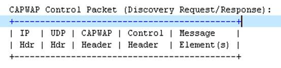
其餘的CAPWAP控制協定資訊必須被DTLS協議加密,因此包括一個CAPWAP DTLS Header。
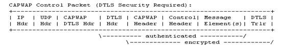
CAPWAP協議對資料包文的DTLS加密是可選的。
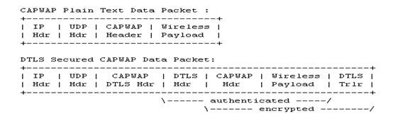
CAPWAP頭部格式:
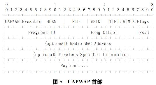
¢ UDP頭:所有的CAPWAP資訊都被封裝在UDP或者UDP-Lite(ipv6)中。
¢ CAPWAP DTLS頭:所有的被DTLS加密的CAPWAP資訊都有該頭部首碼。
¢ DTLS頭:DTLS頭部為CAPWAP的載荷提供認證和加密服務。DTLS在RFC4347中定義。
¢ CAPWAP頭:所有的CAPWAP協議資訊都用同一個頭部,該頭部位於CAPWAP預判碼或者DTLS頭之後。
¢ 無線載荷:包含無線載荷的CAPWAP協議資訊稱為CAPWAP資料包文。CAPWAP協議並沒有對無線載荷的格式做強制要求,而是由無線協議標準決定。
¢ 控制頭:CAPWAP協定包含一個信號元件,稱為CAPWAP控制協議。所有的CAPWAP控制資訊都包含一個控制頭,CAPWAP資料包文則不包含該頭部。
¢ 消息元素:CAPWAP控制資訊包含一個或者多個消息元素,這些跟在元素在控制頭之後。這些消息元素以TLV格式出現(類型/長度/值)
2.5.9.2.1 預判碼
2 種 CAPWAP 首部的前 8 位為預判碼,用於快速判斷此資訊是否經過 DTLS 加密。前 4 位指明 CAPWAP 版本,目前的版本號為 0;後 4 位值為 1 時是 CAPWAP DTLS 首部,值為 0 時是 CAPWAP 首部。
0
0 1 2 3 4 5 6 7
+-+-+-+-+-+-+-+-+
|Version| Type |
2.5.9.2.2 CAPWAP DTLS 首部
標識此資訊經過 DTLS 加密。長度為 32 位,包括 8 位預判碼和 24 位預留碼。
0 1 2 3
0 1 2 3 4 5 6 7 8 9 0 1 2 3 4 5 6 7 8 9 0 1 2 3 4 5 6 7 8 9 0 1
+-+-+-+-+-+-+-+-+-+-+-+-+-+-+-+-+-+-+-+-+-+-+-+-+-+-+-+-+-+-+-+-+
|CAPWAP Preamble| Reserved |
+-+-+-+-+-+-+-+-+-+-+-+-+-+-+-+-+-+-+-+-+-+-+-+-+-+-+-+-+-+-+-+-+
2.5.9.2.3 CAPWAP 首部
CAPWAP 協議的所有資訊都包含 CAPWAP 首部,在控制通道收到則是控制資訊,在資料通道收到則是資料包文,
0 1 2 3
0 1 2 3 4 5 6 7 8 9 0 1 2 3 4 5 6 7 8 9 0 1 2 3 4 5 6 7 8 9 0 1
+-+-+-+-+-+-+-+-+-+-+-+-+-+-+-+-+-+-+-+-+-+-+-+-+-+-+-+-+-+-+-+-+
|CAPWAP Preamble| HLEN | RID | WBID |T|F|L|W|M|K|Flags|
+-+-+-+-+-+-+-+-+-+-+-+-+-+-+-+-+-+-+-+-+-+-+-+-+-+-+-+-+-+-+-+-+
| Fragment ID | Frag Offset |Rsvd |
+-+-+-+-+-+-+-+-+-+-+-+-+-+-+-+-+-+-+-+-+-+-+-+-+-+-+-+-+-+-+-+-+
| (optional) Radio MAC Address |
+-+-+-+-+-+-+-+-+-+-+-+-+-+-+-+-+-+-+-+-+-+-+-+-+-+-+-+-+-+-+-+-+
| (optional) Wireless Specific Information |
+-+-+-+-+-+-+-+-+-+-+-+-+-+-+-+-+-+-+-+-+-+-+-+-+-+-+-+-+-+-+-+-+
| Payload …. |
+-+-+-+-+-+-+-+-+-+-+-+-+-+-+-+-+-+-+-+-+-+-+-+-+-+-+-+-+-+-+-+-+
資訊各部分組成如下:
(1)CAPWAP Preamble:8 位預判碼。
(2)HLEN:5 位首部長度,指明 CAPWAP 首部的長度。
(3)RID:5 位射頻識別字,指明此資訊的來源射頻。
(4)WBID:5 位無線訊框識別字, 指明無線框架類型, 有 IEEE802.11, IEEE802.16 和 EPCGlobal 3 種。
(5)T:1 位元資料訊框識別字,值為 1 時資料訊框是由 WBID指明的類型,值為 0 時是 IEEE802.3 數據訊框。
(6)F:1 位元分組標誌,值為 1 時此資訊是一個 CAPWAP資訊分組,需要和其他分組重組成完成的資訊。
(7)L:1 位元分組結束標誌,值為 1 時此資訊是最後一個分組。
(8)W:1 位元選項標誌,值為 1 時存在 Wireless Specific Information 選項。
(9)M:1 位元選項標誌,值為 1 時存在 Radio MAC Address選項。
(10)K:1 位元存活標誌,指明此資訊用於保持連接存活,不能攜帶使用者資料。
(11)Flags:3 位元預留標誌。
(12)Fragment ID:16 位分組識別字,識別不同的資訊分組,ID 相同的分組屬於同一個 CAPWAP 資訊。
(13)Fragment Offset:13 位分組位移,各分組在該CAPWAP 資訊中的位置。
(14)Reserved:3 位預留碼。
(15)Radio MAC Address:32 位射頻 MAC 地址,不足32 位以全 0 填充。指明資訊來源射頻的 MAC 地址。
(16)Wireless Specific Information:32 位元特殊無線資訊,不足 32 位以全 0 填充。包含特殊資訊,如與 IEEE 802.11, IEEE802.16 和 EPCGlobal 的關聯等。
(17)Payload:資料包文是使用者資料,控制資訊則是控制消息,詳細的控制消息定義參見文獻[1]。
2.5.9.3CAPWAP資料包文
CAPWAP資料包文有兩種類型:CAPWAP Data channel Keep-Alive 資訊和Data Payload資訊。CAPWAP Data hannel Keep-Alive資訊用於同步控制和資料通道,維持資料通道的連接。Data Payload資訊用於在WLC和AP之間傳輸使用者資料。
2.5.9.3.1 CAPWAP Data Channel Keep-Alive
該資訊的目的在於保持通道的可用性。當DatWLChannelKeepAlive計時器到期,AP發送該資訊,同時設置DatWLChannelDeadInterval計時器。
在資訊中,除了HELN欄位和K標誌位元,其餘欄位和標誌位元均被置為0。當收到KEEPALIVE資訊,WLC將回應一個KEEPALIVE資訊給AP。
AP在收到WLC回應的KEEPALIVE資訊後,取消DatWLChannelDeadInterval計時器並且重設DatWLChannelKeepAlive計時器。然後AP將KEEPALIVE資訊當做控制消息進行重發。如果在DatWLChannelDeadInterval計時器到期時仍然沒有收到WLC的回應資訊,AP將刪除DTLS的控制SESSION,如果存在資料SESSION也同時刪除。
KEEPALIVE資訊格式如下所示:
0 1 2 3
0 1 2 3 4 5 6 7 8 9 0 1 2 3 4 5 6 7 8 9 0 1 2 3 4 5 6 7 8 9 0 1
+-+-+-+-+-+-+-+-+-+-+-+-+-+-+-+-+-+-+-+-+-+-+-+-+-+-+-+-+-+-+-+-+
| Message Element Length | Message Element [0..N] …
+-+-+-+-+-+-+-+-+-+-+-+-+-+-+-+-+-+-+-+-+-+-+-+-+-+-+-+-+-+-+-+-+
資訊被封裝在CAPWAP資訊的payload欄位中。
Message Element Length: 16bit的長度欄位,最大為65535。
Message Element[0..N]: 攜帶的KEPPALIVE資訊資料,SEESION ID是必須攜帶的。
2.5.9.3.2 Data Payload
CAPWAP Data Payload資訊封裝了需要轉發的使用者資料,裡面可能是802.3訊框也有可能是無線資料訊框,參見3.2章節。
2.5.9.3.3 DTLS資料通道的建立
如果WLC和AP被配置為DTLS隧道傳輸模式,那麼就必須初始化DTLS SESSION。為了避免重新鑒定、認證WLC和AP,DTLS資料通道應該利用TLS SESSION的特徵。
WLC DTLS實現不應該在沒有控制通道的情況下初始化資料通道SESSION。
2.5.9.4 CAPWAP控制資訊
CAPWAP控制資訊分為以下幾種類型:
Discovery:發現網路中的WLC,WLC位置和能力
Join:AP用於向WLC請求服務,WLC用於回應AP
Control Channel Management:維持控制通道
AP Configuration Management:WLC給AP發送設定檔。
Station Session Management:WLC發送station策略給AP
Device Management Operations:請求和發送firmware給AP
Binding-Specific CAPWAP Management Messages: WLC和AP用於切換式通訊協定指定的CAPWAP管理資訊。可能交換一個station的連接狀態資訊。
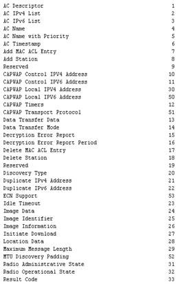
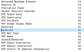
2.5.9.3.1 CAPWAP Discovery Operations
¢ Discovery Request Message
AP用Discovery Request來自動發現網路中可用的WLC,提供自己的基本性能給WLC。
¢ Discovery Response Message
WLC使用Discovery Response,將自己支援的服務告訴給請求服務的AP。
¢ Primary Discovery Request Message
AP發送Primary Discovery Request用於:判斷它首選(或者配置的)的WLC是否可用或者執行一個Path MTU Discovery
¢ Primary Discovery Response
WLC使用Primary Discovery Response告訴AP自己當前可用,與支援服務。
當AP被配置了一個首選的WLC,但是現在卻連接在另外一個WLC上,此時會發送Primary Discovery Request。因為AP只有一個CAPWAP狀態機,AP在run狀態發送Primary Discovery Request,WLC不傳輸這個消息
2.5.9.3.2 CAPWAP Join Operations
¢ Join Request
在與WLC建立DTLS連接之後,AP使用Join Request來向一個WLC請求服務
¢ Join Response
WLC使用Join Response告知AP是否會向其提供服務
2.5.9.3.3 Control Channel Management
¢ Echo Request
¢ Echo Response
Echo Request和Echo Response用於在控制資訊沒有發送的時候,來顯式的維持控制通道的連接
2.5.9.3.4 AP Configuration Management
¢ Configuration Status Request
AP用於發送自己當前的配置給WLC
¢ Configuration Status Response
WLC提供自己的配置資料給AP,覆蓋AP所請求的配置
¢ Configuration Update Request
run狀態的時候,WLC發送給AP用於修改AP上的配置。
¢ Configuration Update Response
回應Configuration Update Request
¢ Change State Event Request
1:當AP收到來自WLC的Configuration Status Response,AP使用Change State Event Request來提供AP radio的當前狀態,確認WLC提供的配置已經成功應用
2:在run狀態下,AP發送Change State Event Request來告訴WLC,AP radio發生了意料之外的改變。
¢ Change State Event Response:
回應Change State Event Request
¢ Clear Configuration Request:
WLC用於請求AP將自己的配置恢復至出廠預設值
¢ Clear Configuration Response
AP恢復出廠預設值後,發送給WLC的確認。
CAPWAP協定提供彈性的AP配置管理機制,有兩種方法:
1:AP沒有任何配置,接受WLC提供的任何配置
2:AP保存WLC提供的靜態記憶體中的不是預設值的配置資料,然後重啟初始化配置。
2.5.9.3.5 Device Management Operations(可選)
¢ Image Data Request
在AP和WLC之間交換,用於AP下載一個新的firmware
¢ Image Data Response
回應Image Data Response
¢ Reset Request
要求AP進行重啟。
¢ Reset Response
回應Reset Request
¢ AP Event Request
AP用來發送資訊給WLC。AP Event Request可能是階段性發送,或者是作為一個AP同步事件的響應。
¢ AP Event Response
回應AP Event Request
¢ Data Transfer Request
將AP上的調試資訊發送給WLC
¢ Data Transfer Response
回應 Data Transfer Request
AP Event Request是AP發送一些定義好的狀態資訊,如Decryption Error Report,Duplicate IPv4 Address等等,也能用於發送Vendor Specific Payload
Data Transfer Request可以由WLC發送,也可以由AP發送。
2.5.9.3.6 CAPWAP定義的firmware下載過程:

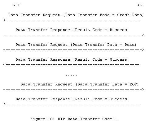
firmware的下載可以發生在image data狀態或者run狀態。CAPWAP協議並沒有提供讓WLC來識別是否AP提供的firmware資訊是否正確,或者AP是否正確存儲了firmware。
2.5.9.3.7 Station Session Management
¢ Station Configuration Request
WLC用於創建,修改,刪除AP上的staion 會話狀態
¢ Station Configuration Response
回應Station Configuration Request
L3 CAPWAP(Support after 5.2 fireware)
UDP src port 1024——ENCRYPTED Control —— UDP dst port 5247
UDP src port 1024——ENCAPSULATED DATA—— UDP dst port 5247
Phase 1 Discovery Phase
- AP 啟動時進行搜尋及探測的程式(Zero-touch 部署)
LAP 通過不同方式建立關於所有 management interfWLCe ip 位址 的資料庫
1.1 本地廣播方式
1.2 本身所存放的上次成功的WLC IP位址
(AP Priming 當AP和 WLC 結合時 AP 可乎學到 WLC 的IP 位址及
在mobility 中WLC 成員的IP位址)
1.3 利用DHCP及option 43 提供的位址
(DHCP vendor option AP 送出帶有 VENDOR Option的要求,而如DHCP
Server 有設定回應這些 Option 則在回WLCK 時會送回Controller的IP
清單)
1.4 DNS 中記錄的CISCO-CAPWAP-CONTROLLER
(AP可由DHCP Option 獲得 DNS的訊息,並且由訊息內得到Controllers
的IP 位址,AP將利用這些訊息來進行DNS 查訪
CISCO-CAPWAP-CONTROLLLER 所對應到的 mgmt. interfWLCe 位址)
- AP 找到 WLC 加入
2.1 加入 首要控制器,如果它曾經是蓄勢待發的WLC
2.2 首要Controller 失敗則嘗試 第二而及第三順位蓄勢待發的WLC
2.3 如沒蓄勢待發的WLC在AP中,則AP將查找 Master Contreoller (主控
器)
2.4 如沒有蓄勢待發的WLC及 MASTER CONTRLLER AP 將從所有回應控制
器中選擇具有最小負載的AP Management 介面
- WLC 送出 WLC 版本程式,及相關參數
- 完成後 AP 開始支援 Wireless Client
AP CAPWAP JOIN Message
AP get WLC discovery reply
AP & eWLCh Discovered Controller handshake to Create IETF DTLS Tunnel
AP then Determine Which one Controller to Join and send Join message
via created DTLS session
The CAPWAP Join Message request from AP to WLC include
1. Type of Controller (like to Associate)
2. MAC-address of Controller (like to Associate)
3. AP self Hardware and software version
4. AP name
5. The Number & type of radio present on AP
The CAPWAP Join response from WLC to AP
- Request successful (Code 0 )
- Request Failure (Code 1) & may Provide Status Message
Note CAPWAP using Dynamic PMTU , if error CAPWAP use 576 to Send
Message.
CPWAAP Configuration Phase
AP —CAPWAP Configuration Request ——à WLC
list configuration parameter and value of AP
ß——–Configuration Response——–
Configuration setting base on controller
(can over write configuration request &
return configured Command PWLCket,AP received
then evaluated eWLCh configuration element and
implementation those element)
Wireless World Mode , 802.11H and Cisco DTPC
Aside
1:World Mode is about is “the list of allowed channels in this country" and “the power level ranges allowed in this country".
World mode is actually a Cisco implementation of the 802.11d
802.11d protocol allows you to send the regulatory domain information to you client, which is going to adapt to them.
The 802.11d protocol was integrated into the 802.11-2007 standard, thus allowing the possibility to send this information, without stating exactly how it could be sent.
In a Cisco network, this can be contained in the Vendor Specific fields of the beacons. So where is that feature in the Autonomous APs?
In the radio (802.11b / 802.11a) configuration page.
And in the Unified solution? Nowhere… what? did they forget it? Naahh, can’t believe that… read further….
2:TPC, Transmit Power Control, is actually a feature of 802.11h… You know 802.11h? This protocol that prevents your APs working outdoor on the 5 Ghz spectrum from interfering with airport radars… this protocol has two sides:
.2-1 DFS, Dynamic Frequency Selection, that makes that if your AP
hears a radar blast on its current frequency, it sends a “changing
channel" 802.11h message and jumps to another channel.
.2-2 TPC, Transmit Power Control, by which 2 devices initiating a
communication in the 5 Ghz spectrum will negotiate so that
their respective power level is as low as possible, just loud
enough to hear each other (so that your noisy 50 mW access p
point does not disturb the poor 60 WATTS radar sitting next
door!!).
Where do you configure TPC? Well, you don’t really configure it. It is part of 802.11h, and your 802.11a device has to be compliant with it, and implements it automatically.
3:-DTPC, that’s Dynamic Transmit Power Control, looks close to TPC
hey? But this is Cisco stuff, not 802.11 something anymore. With DTPC, your Cisco access point transmits to your Cisco CCX compliant client information about which power level to use… looks somehow close to World mode, don’t you think?
Yes, it’s close… but do you know what caused the death of World mode and why you don’t find this feature in a controller? Think about it… what does it exactly do? If (yes, “if"), you enable it, your clients will receive a pack of allowed channels and power levels from your AP. This information format is proprietary, so your client needs to be a CCX guy to understand it. And what does it do with that information? You don’t know… your client may use it, if it is also configured for World mode. It may understand it but not use it, if it is CCX but not configured for World mode, it may not be able to use it if its drivers is not per-set for this regulatory domain, or it may not even understand it if the client CCX version is too old or if the client is not CCX… Whoa, what a result… so let’s think about another approach.
If your client is CCX, you can actually do more: influence it. very often, your AP has a good 9 dBi patch antenna and your client has a poor rubber duck 2.2 dBi antenna. Your client hears the AP well, but the client signal is lost in the surrounding noise and your AP does not hear it well. Your client should increase its power level, but it does not know that the AP does not hear it well… all it knows is that it (the client) hears the AP well, and from this received signal deduces its own power level. If you client is CCX, the AP can tell to your client “I don’t hear you well, increase your power to 20 mW", or “hey no need to shout! reduce your power to 5 mW, that will save your battery". In this information, the AP can communicate maximums (“increase your power again, but don’t go beyond 50 mW"). Isn’t that better than World mode? That’s what DTPC is about. You can enable it in your controller from the Main radio menu (Wireless > 802.11a > Network, in the General field).
But what about the channels? Well, there is also another CCX feature by which an AP can tell a CCX client “don’t scan, you are in my cell in a comfort zone, stay quiet and save battery". Or “your signal strength is decreasing, you should start scanning", and there are a lot of variation from there, from “scan channels 1,6,11″ or “check channel 6, Ap aa:bb:cc:dd:ee:ff should be there"… isn’t that even better?
Yes, but what about the non-CCX clients? Well, they would not have understood the World mode messages anyway, this is why CCX is cool…
擷錄於 Jerome Henry BLOGR Article
IOS XR Fundamental
Aside
CISCO IOS XR
© October 2012
 Table of Contents
1.
Cisco IOS XR Introduction and Comparison to IOS
2.
Cisco IOS XR Prompt and Hostname Differences
3.
Basic Configuration Options
4.
Configuring an Interface – Basic IPv4 and IPv6 address
5.
Bundled Interfaces
6.
Software Installation and PIE packages
7.
Licensing
8.
Aliases
9.
Wildcard Masks
10.Processes
11.Remote Access Services – Telnet and SSH
12.TACACS Configuration ( default and non-default VRF)
13.Access Lists
14.OSPF
15.EIGRP
16.RIP
17.IS-IS
18.BGP – iBGP and eBGP
19.Route Filtering
20.VRF lite and Dot1Q Trunks
21.Basic MPLS – LDP
22.MPLS VPN
23.L2VPN
24.NHRP (HSRP/VRRP)
There are two topologies that have been used. This is because of what I had access to changed over time. For this lab, here is a topology diagram of what was used:
ASR9000 and Cisco 2811
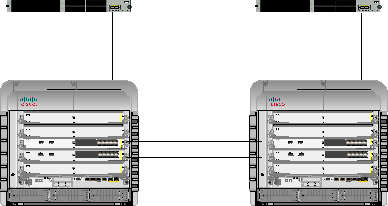 CE1 / R3 CE2 / R4
S S L L O
O T A= ACT F= FDX T 2 S= SPEED L= LINK
3
A FE 0/1 FE 0/0 A
R
Cisco 2811
S S L L O
O T A= ACT F= FDX T 2 S= SPEED L= LINK
3
A FE 0/1 FE 0/0 A
R
Cisco 2811
N M E 0
F S S S
L L
O O L T T
1 0
F S L
PVDM1 PVDM2 AIM1 AIM0
N M E 0
F S S S
L L
O O L T T
1 0
F S L
PVDM1 PVDM2 AIM1 AIM0
F0/0 F0/0
Cisco ASR 9000 Series
Cisco ASR 9000 Series
A/L
0
A/L
1
 1 3 5 7 9 11 13 15 17 19
L L
G0/1/0/11 G0/1/0/11
A/L
0
A/L
1
 1 3 5 7 9 11 13 15 17 19
L L
A/L
0
A/L
1
0 2 4 6 8 10 12 14 16 18
 1 3 5 7 9 11 13 15 17 19
L L
G0/0/0/11
G0/0/0/11
A/L
0
A/L
1
0 2 4 6 8 10 12 14 16 18
 1 3 5 7 9 11 13 15 17 19
L L
0 2 4 6 8 10 12 14 16 18
0 2 4 6 8 10 12 14 16 18


 S S
S S
PE1 / R1 PE2 / R2
Cisco 12000
 R1
R1
Cisco 12000 SERIES
R2
Cisco 12000 SERIES
0 1 2 3 CSCO CSC1
4 5 6 7
0 1 2 3 CSCO CSC1
4 5 6 7
LINK
LINK
SLOT 0 SLOT 1 SLOT 0 SLOT 1
LINK
3
LINK
5
RESET RESET


 LINK COLL LINK COLL TX RX TX RX
G0/3/0/2 G0/5/0/2
G0/3/0/3 G0/5/0/3
SLOT 0 SLOT 1 SLOT 0 SLOT 1

 RESET RESET

 LINK COLL LINK COLL
LINK
3
LINK
5
TX RX TX RX
MII RJ45 MII RJ45
MII RJ45 MII RJ45

 7
7
 7
7
 LINK
LINK
8 8 8 8 8 8 8 8 8 8 8 8
8 8 8 8 8 8 8 8 8 8 8 8

 8 8 8 8 8 8 8 8
8 8 8 8 8 8 8 8
LINK
8 8 8 8
8 8 8 8
1. Cisco IOS XR Introduction and
 Comparison to IOS
Let’s start with the basic difference between Cisco IOS and Cisco IOS XR
code, the Operating System.(IOS 及 IOS XR 的基本差異)
In Cisco IOS, the kernel is monolithic, meaning everything in installed in a single image and all processes share the same address space. There is no memory protection between processes, so if one crashes it can impact all other processes on the box – thus forcing or causing a reload of the entire router. The other thing with monolithic code is that it has a run to completion scheduler, so the kernel will not preempt a process that is running; the process must make a kernel call before another process has a chance to execute.
 In Cisco IOS XR, the kernel is based on an OS called QNX Neutrino that runs some very powerful and reliable systems. QNX runs – per their News Release at http://www.qnx.com/news/pr_1329_3.html
– things from EKG machines, to Air Traffic Control systems, and among other things – automated beer bottle inspection systems. IOS XR offers modularity and memory protection between processes, threads and supports preemptive scheduling as well as the ability to restart a failed process. Protocols like BGP, OSPF, OSPFv3, RIBv4, RIBv6, etc all run in separate spaces – if one has a fault, it will not impact the others. Also, an added bonus, if you run multiple routing protocol instances (like OSPF), each process will run in its own memory space – this is an important feature of Service Providers – any fault with one customer process will not impact another.
Another big difference between IOS and IOS XR is the configuration model. IOS is a single stage model meaning that as soon as you make a change, it is applied to the active running config. With IOS XR, you have a running
(active) config that you cannot modify directly, all your changes are made in
a staging area first before being committed to the running config. After you make your changes, you commit them and promote the staging config to the active config. Before the change is made active, the IOS XR will run a sanity check on it making sure that the commands are correct to a certain degree, if there is a problem it will tell you so that you can correct the error
% Failed to commit one or more configuration items. Please use ‘show configuration failed’ to view the errors
Here is a table of some of the other significant differences between IOS and
IOS XR
|
IOS XR IOS |
|
Config changes do not Configuration changes take take place immediately place immediately |
|
Config changes must be No commit, changes COMMITted before taking immediate effect |
|
You can check your No verification, immediate. configuration before applying it |
|
Two stage configuration Single stage |
|
Configuration Rollback Not easy to do, has to be manually configured and not guaranteed |
|
Feature centric Interface centric |
2. Cisco IOS XR Prompt and Hostname
 Differences
Let’s cover the prompt real quick as that is a bit different than what people are used to.
Let’s look at the standard IOS prompt vs. the IOS XR prompt.
IOS: Router#
IOS-XR: RP/0/7/CPU0:ios#
As you can see the prompt is a bit different. In standard IOS you have the hostname, but in IOS XR you get a bit more information. It breaks down as follows:
Prompt Syntax:
Type – type of interface card (Usually RP for Route Processor)
Rack – What Rack number this is installed in in a multishelf system, typically 0 if standalone
Slot – Slot the RP is installed in (7 in this example)
Module – What execute the user commands or port interface. Usually CPU0 or CPU1
Name – Hostname of the router, default here is IOS
 Ok, now let’s change the hostname on typical IOS so you can see the difference. Going forward, BLUE text is prompts and router feedback, RED are commands entered.
Router#
Router#conf t
*Mar 29 16:32:51.507: %SYS-5-CONFIG_I: Configured from console by console Enter configuration commands, one per line. End with CNTL/Z. Router(config)#hostname R1
R1(config)#
As you can see, in IOS the hostname changed immediately after hitting Enter.
So, let’s change the hostname to R1 on IOS XR code:
RP/0/7/CPU0:ios#
RP/0/7/CPU0:ios#conf t
Thu Mar 29 16:00:43.844 UTC
RP/0/7/CPU0:ios(config)#hostname R1
RP/0/7/CPU0:ios(config)#
Notice that the hostname did not change? In IOS XR you need to COMMIT your changes in order for them to take effect. But before we commit them, let’s do a show config quick
RP/0/7/CPU0:ios(config)#
RP/0/7/CPU0:ios(config)# sh config
Thu Mar 29 16:03:53.060 UTC Building configuration…
!! IOS XR Configuration 4.1.1
hostname R1 end
RP/0/7/CPU0:ios(config)#
Pretty cool, the router will show you the changes you are about to make, this is your staging config changes.
Now we can COMMIT the changes
RP/0/7/CPU0:ios(config)#commit Thu Mar 29 16:03:04.182 UTC RP/0/7/CPU0:R1(config)#
 See, once you entered COMMIT, the hostname change from IOS to R1.
 3. Basic Configuration Options
Ok, we have seen the basic COMMIT option – but what other options do we have for configuration mode? Well, we have a few to choose from.
First, what if I am making changes and decide I don’t want them? You have a
few options. First you could just exit all the way out.
RP/0/7/CPU0:R1(config)#exit
Uncommitted changes found, commit them before exiting(yes/no/cancel)?
[cancel]: no
And once you exit out, all your changes are lost.
Ok, that is one option. Another is clear. To demonstrate we will create loopback 666:
RP/0/7/CPU0:R1#conf t
Sun Apr 1 22:18:52.956 UTC RP/0/7/CPU0:R1(config)#int loop666
RP/0/7/CPU0:R1(config-if)#ip add 6.6.6.6/32
Ok, let’s check the candidate configuration:(檢查已經設定但未確認之設定)
RP/0/7/CPU0:R1(config-if)#show config
 Sun Apr 1 22:19:03.438 UTC Building configuration…
!! IOS XR Configuration 4.1.1 interface Loopback666
ipv4 address 6.6.6.6 255.255.255.255
!
end
RP/0/7/CPU0:R1(config-if)#
OK, we have it in the candidate configuration now. We changed our mind about that – so lets clear it.
RP/0/7/CPU0:R1(config-if)#clear
Now check the candidate configuration again. RP/0/7/CPU0:R1(config)#show config
Sun Apr 1 22:19:34.733 UTC Building configuration…
!! IOS XR Configuration 4.1.1
end
RP/0/7/CPU0:R1(config)# There, all gone!
Now, what if we want to make a change but we want to be sure we don’t lose connection to the router? Well, we can do a commit confirm, this way if we do lose connection our change will be rolled back!
RP/0/7/CPU0:R1#conf t
Sun Apr 1 22:23:01.154 UTC RP/0/7/CPU0:R1(config)#int loop 666
RP/0/7/CPU0:R1(config-if)#ip add 6.6.6.6/32
Now, lets look at our commit confirmed options: RP/0/7/CPU0:R1(config-if)#commit confirmed ?
<30-65535> Seconds until rollback unless there is a confirming commit minutes Specify the rollback timer in the minutes
<cr> Commit the configuration changes to running
See, we can have a few seconds or a few minutes. Pretty cool! RP/0/7/CPU0:R1(config-if)#commit confirmed 30
Sun Apr 1 22:23:19.344 UTC
Now, lets see if we have loop666: RP/0/7/CPU0:R1(config-if)#do show int loop666
Sun Apr 1 22:23:34.353 UTC
Loopback666 is up, line protocol is up
Interface state transitions: 1
Hardware is Loopback interface(s) Internet address is 6.6.6.6/32
 MTU 1500 bytes, BW 0 Kbit
reliability Unknown, txload Unknown, rxload Unknown
Encapsulation Loopback, loopback not set,
Last input Unknown, output Unknown
Last clearing of “show interface" counters Unknown
RP/0/7/CPU0:R1(config-if)#
Yup, its there. Now we can wait a few seconds (30 or so) and do the show interface command again.
RP/0/7/CPU0:R1(config-if)#do show int loop666
Sun Apr 1 22:25:09.361 UTC Interface not found (Loopback666)
RP/0/7/CPU0:R1(config-if)# All gone!
Ok, now lets commit it this time. RP/0/7/CPU0:R1#conf t
Sun Apr 1 22:26:20.749 UTC RP/0/7/CPU0:R1(config)#int loop666
RP/0/7/CPU0:R1(config-if)#ip add 6.6.6.6/32
RP/0/7/CPU0:R1(config-if)#commit confirmed 30
Sun Apr 1 22:26:32.913 UTC RP/0/7/CPU0:R1(config-if)#
Lets see if the interface is there: RP/0/7/CPU0:R1(config-if)#do show int loop666
Sun Apr 1 22:26:38.421 UTC
Loopback666 is up, line protocol is up
Interface state transitions: 1
Hardware is Loopback interface(s) Internet address is 6.6.6.6/32
MTU 1500 bytes, BW 0 Kbit
reliability Unknown, txload Unknown, rxload Unknown
Encapsulation Loopback, loopback not set, Last input Unknown, output Unknown
Last clearing of “show interface" counters Unknown
Yup, now we can commit it again to make it stay. RP/0/7/CPU0:R1(config-if)#commit
 % Confirming commit for trial session. RP/0/7/CPU0:R1(config-if)#
And lets make sure it is still there. RP/0/7/CPU0:R1#sh int loop 666
Sun Apr 1 22:27:09.232 UTC
Loopback666 is up, line protocol is up
Interface state transitions: 1
Hardware is Loopback interface(s)
Internet address is 6.6.6.6/32
MTU 1500 bytes, BW 0 Kbit
reliability Unknown, txload Unknown, rxload Unknown
Encapsulation Loopback, loopback not set, Last input Unknown, output Unknown
Last clearing of “show interface" counters Unknown
RP/0/7/CPU0:R1#
Look at that, IOS XR has a commit confirmed – just like someone else does as well.
Few other things that is nice to know.
You can configure the system in exclusive mode, this way only you can be making changes and nobody else. To do this, just enter configure exclusive
RP/0/7/CPU0:R1#configure exclusive
You can add comments and notations to your commit that will show up in the rollback.
RP/0/7/CPU0:R1#conf t
Sun Apr 1 22:32:23.941 UTC
RP/0/7/CPU0:R1(config)#int loop 667
RP/0/7/CPU0:R1(config-if)#ip add 6.6.6.7/32
RP/0/7/CPU0:R1(config-if)#exit
RP/0/7/CPU0:R1(config)#commit comment Created Loopback 667 For Testing
Sun Apr 1 22:33:34.589 UTC RP/0/7/CPU0:R1(config)#
Now, if a comment has been added, you can see it via the show configuration history last x detail command
RP/0/7/CPU0:R1#sh configuration history last 1 detail
Sun Apr 1 22:36:04.053 UTC
1) Event: commit Time: Sun Apr 1 22:33:36 2012
Commit ID: 1000000230 Label:
User: user Line: con0_7_CPU0
Client: CLI Comment: Created Loopback 667 For Testing
RP/0/7/CPU0:R1#
Ok, let’s quickly look at loading a configuration from the disk and overwriting an existing configuration.
I have copied a config to disk0a: called newconfig.txt. What I want to do is install this configuration as the running config on the router.
1626 -rwx 204 Wed Oct 17 01:21:30 2012 newconfig.txt
So to start, lets delete the existing configuration
RP/0/RSP0/CPU0:R1(config)#commit replace
Wed Oct 17 01:21:43.406 UTC
This commit will replace or remove the entire running configuration. This operation can be service affecting.
Do you wish to proceed? [no]: y RP/0/RSP0/CPU0:ios(config)# RP/0/RSP0/CPU0:ios(config)#exit
Ok, so now we are at an unconfigured device. Now we can load the config on the disk to the running config.
RP/0/RSP0/CPU0:ios(config)#load disk0a:/newconfig.txt
Loading.
204 bytes parsed in 1 sec (203)bytes/sec
The configuration is now loaded into the candidate config. Let us check what is there and then commit it.
RP/0/RSP0/CPU0:ios(config)#show confi
Wed Oct 17 01:26:17.539 UTC
Building configuration…
!! IOS XR Configuration 4.1.2 hostname R1
domain name lab.cfg interface Loopback100
ipv4 address 100.100.100.100 255.255.255.255
!
end
RP/0/RSP0/CPU0:ios(config)#commit Wed Oct 17 01:26:22.174 UTC RP/0/RSP0/CPU0:R1(config)#
There, we have loaded the config and applied the changes.
 I have loaded another file to the router called ReplaceConfig.txt. This is a new configuration for the router, one that we want to replace the existing config with.
RP/0/RSP0/CPU0:R1#conf t
Wed Oct 17 01:37:23.638 UTC
RP/0/RSP0/CPU0:R1(config)#load disk0a:/ReplaceConfig.txt
Loading.
283 bytes parsed in 1 sec (282)bytes/sec
RP/0/RSP0/CPU0:R1(config)#show config
Wed Oct 17 01:37:38.571 UTC Building configuration…
!! IOS XR Configuration 4.1.2 hostname Router1
domain name NewLab.CFG
interface Loopback100
ipv4 address 101.101.101.101 255.255.255.255
!
interface TenGigE0/0/0/0
ipv4 address 200.200.200.202 255.255.255.0
!
end
RP/0/RSP0/CPU0:R1(config)#commit replace
Wed Oct 17 01:37:41.577 UTC
This commit will replace or remove the entire running configuration. This operation can be service affecting.
Do you wish to proceed? [no]: y
RP/0/RSP0/CPU0:Router1(config)#
What other options to loaf configuration are there? Well, here is a list: RP/0/RSP0/CPU0:Router1(config)#load ?
WORD Load from file
bootflash: Load from bootflash: file system commit Load commit changes
compactflash: Load from compactflash: file system
compactflasha: Load from compactflasha: file system configuration Contents of configuration
diff Load from diff file
disk0: Load from disk0: file system disk0a: Load from disk0a: file system disk1: Load from disk1: file system disk1a: Load from disk1a: file system ftp: Load from ftp: file system harddisk: Load from harddisk: file system harddiska: Load from harddiska: file system harddiskb: Load from harddiskb: file system lcdisk0: Load from lcdisk0: file system lcdisk0a: Load from lcdisk0a: file system nvram: Load from nvram: file system
rcp: Load from rcp: file system
rollback Load rollback changes
tftp: Load from tftp: file system
RP/0/RSP0/CPU0:Router1(config)#
You can load from the local disk, RCP, TFTP, FTP, etc if you want.
4. Configuring an interface
 Basic IPv4 and IPv6 address
First we will take a look at what interfaces we have and review them quickly. We can use the same IOS command we are already familiar with – show ip interface brief
RP/0/7/CPU0:R1# RP/0/7/CPU0:R1#sh ip int br
|
Thu Mar 29 18:12:04.883
Interface |
UTC
IP-Address |
Status |
Protocol |
|
MgmtEth0/7/CPU0/0 |
unassigned |
Shutdown |
Down |
|
MgmtEth0/7/CPU0/1 |
unassigned |
Shutdown |
Down |
|
MgmtEth0/7/CPU0/2 |
unassigned |
Shutdown |
Down |
|
GigabitEthernet0/3/0/0 |
unassigned |
Down |
Down |
|
GigabitEthernet0/3/0/1 |
unassigned |
Down |
Down |
|
GigabitEthernet0/3/0/2 |
unassigned |
Up |
Up |
|
GigabitEthernet0/3/0/3 |
unassigned |
Up |
Up |
|
MgmtEth0/6/CPU0/0 |
unassigned |
Shutdown |
Down |
|
MgmtEth0/6/CPU0/1 |
unassigned |
Shutdown |
Down |
|
MgmtEth0/6/CPU0/2 |
unassigned |
Shutdown |
Down |
|
RP/0/7/CPU0:R1# |
Here you can see that we have an RP in Slot 6 and 7 (Mgmt) and a 4-port Gig card in Slot 3. For this lab, interfaces G0/3/0/2 and G0/3/0/3 are pre- cabled to another router and are currently UP/UP right now.
Let configure an IP address on G0/3/0/2 of 150.1.12.1 with a mask of
255.255.255.0
First, let’s look at the running config on the interface now:
RP/0/7/CPU0:R1#
RP/0/7/CPU0:R1#sh run int g0/3/0/2
Thu Mar 29 18:38:29.942 UTC
% No such configuration item(s)
RP/0/7/CPU0:R1#
As you can see, it says No such config, it is telling you that it is unconfigured.
RP/0/7/CPU0:R1#conf t
Thu Mar 29 18:38:31.891 UTC RP/0/7/CPU0:R1(config)#int g0/3/0/2
RP/0/7/CPU0:R1(config-if)#ip add 150.1.12.1/24
Notice, on IOS XR you can use / for the subnet, no more entering
255.255.255.0 :
RP/0/7/CPU0:R1(config-if)#show config
Thu Mar 29 18:38:44.248 UTC Building configuration…
!! IOS XR Configuration 4.1.1 interface GigabitEthernet0/3/0/2
ipv4 address 150.1.12.1 255.255.255.0
!
end
RP/0/7/CPU0:R1(config-if)#
Another cool thing with IOS-XR is you can find out where you are any time you want just by entering PWD
RP/0/7/CPU0:R1(config-if)#pwd
Thu Mar 29 19:31:24.666 UTC
interface GigabitEthernet0/3/0/2
RP/0/7/CPU0:R1(config-if)# RP/0/7/CPU0:R1(config-if)#comm
Thu Mar 29 18:38:46.216 UTC
RP/0/7/CPU0:R1#sh run int g0/3/0/2
Thu Mar 29 18:42:43.763 UTC
 interface GigabitEthernet0/3/0/2
ipv4 address 150.1.12.1 255.255.255.0
!
RP/0/7/CPU0:R1#
Let’s PING our neighbor now – 150.1.12.2
RP/0/7/CPU0:R1#ping 150.1.12.2
Thu Mar 29 18:44:39.570 UTC
Type escape sequence to abort.
Sending 5, 100-byte ICMP Echos to 150.1.12.2, timeout is 2 seconds:
!!!!!
Success rate is 100 percent (5/5), round-trip min/avg/max = 3/8/12 ms
RP/0/7/CPU0:R1#
Now, lets configure a loopback for R1 of 1.1.1.1/32
RP/0/7/CPU0:R1#conf t
Thu Mar 29 19:25:19.486 UTC RP/0/7/CPU0:R1(config)#int l0
RP/0/7/CPU0:R1(config-if)#ip add 1.1.1.1/32
RP/0/7/CPU0:R1(config-if)#exit
RP/0/7/CPU0:R1(config)#exit
Uncommitted changes found, commit them before exiting(yes/no/cancel)? [cancel]:yes
RP/0/7/CPU0:R1#
Notice this time I did not commit the change, but the system knew I was making changes and asked me if I wanted to commit them. I simply responded
with YES and it saved them for me. If I did not want to save them, I could have entered NO and all the changes would have been tossed out. If I would have selected CANCEL, I would go back into edit mode.
Now time to configure some IPv6 addresses – first 2001:1:1:12::1/64
RP/0/7/CPU0:R1#conf t
Thu Mar 29 19:26:21.184 UTC RP/0/7/CPU0:R1(cconfig)#int g0/3/0/2
RP/0/7/CPU0:R1(config-if)#ipv6 address 2001:1:1:12::1/64
RP/0/7/CPU0:R1(config-if)#exit RP/0/7/CPU0:R1(config)#commit Thu Mar 29 19:26:39.769 UTC RP/0/7/CPU0:R1(config)#exit
And now we can try to PING our neighbor at 2001:1:1:12::2
RP/0/7/CPU0:R1#ping 2001:1:1:12::2
Thu Mar 29 19:29:11.893 UTC Type escape sequence to abort.
Sending 5, 100-byte ICMP Echos to 2001:1:1:12::2, timeout is 2 seconds:
!!!!!
Success rate is 100 percent (5/5), round-trip min/avg/max = 2/16/68 ms
RP/0/7/CPU0:R1#
Let’s add one under our loopback interface as well – well use 2001::1/128
RP/0/7/CPU0:R1#conf t
RP/0/7/CPU0:R1(config)#int l0
RP/0/7/CPU0:R1(config-if)#ipv6 add 2001::1/128
RP/0/7/CPU0:R1(config-if)#commit Thu Mar 29 19:30:49.920 UTC RP/0/7/CPU0:R1(config-if)#
 5. Interface Bundles
Etherchannels are also different between IOS and IOS XR. In typical IOS, they would be configured as such:
interface port-channel 1
IP add 10.1.1.1 255.255.255.0 interface FastEthernet0/0 channel-group 1
interface FastEthernet0/1 channel-group 1
IOS XE is a little different then IOS as you can choose LACP:
interface GigabitEthernet0/0/2 channel-group 12 mode active no shut
interface GigabitEthernet0/0/3
channel-group 12 mode active
no shut
interface Port-channel12
ip address 10.1.1.1 255.255.255.252
And with IOS XR, it is a bit different again. So, for this example we will configure Ethernet Bundle 200
 First on PE2: RP/0/RSP0/CPU0:PE2#conf t
First up though, let’s reset the interfaces back to factory by using the no
interface command:
RP/0/RSP0/CPU0:PE2(config)#no int g0/0/0/11
RP/0/RSP0/CPU0:PE2(config)#commit
Instead of a port-channel interface, we do a bundle-ether interface
RP/0/RSP0/CPU0:PE2(config)#int bundle-ether 200
RP/0/RSP0/CPU0:PE2(config-if)#ip add 150.1.12.2 255.255.255.0
Now let’s look at our bundle options:
RP/0/RSP0/CPU0:PE2(config-if)#bundle ?
load-balancing Load balancing commands on a bundle
maximum-active Set a limit on the number of links that can be active minimum-active Set the minimum criteria for the bundle to be active shutdown Bring all links in the bundle down to Standby state wait-while Set the wait-while timeout for members of this bundle
Ok, since this is a bundle, we should put restrictions around the max and min links. Normally this is not a problem, but if you had to guarantee bandwidth (say 4G, then you might consider having the min links set to 4, and if you dropped below 4 the interface would go down).
RP/0/RSP0/CPU0:PE2(config-if)#bundle maximum-active links 2
RP/0/RSP0/CPU0:PE2(config-if)#bundle minimum-active links 1
Now let’s take a quick look at our load balancing hash options: RP/0/RSP0/CPU0:PE2(config-if)#bundle load-balancing hash ?
dst-ip Use the destination IP as the hash function
src-ip Use the source IP as the hash function
So, for this example we will use the src-ip
RP/0/RSP0/CPU0:PE2(config-if)#bundle load-balancing hash src-ip
Now, let’s assign the interfaces to the bundle
RP/0/RSP0/CPU0:PE2(config-if)#int g0/1/0/11
Just like port-channels, the bundle ID should match the interface number you created. But here we will also look at what bundle options we have: RP/0/RSP0/CPU0:PE2(config-if)#bundle id 200 mode ?
active Run LACP in active mode over the port.
on Do not run LACP over the port.
passive Run LACP in passive mode over the port.

 There are three ways that LACP will link aggregate:
|
Switch |
1 |
Switch 2 |
Notes |
|
Active |
Active |
This is the recommended configuration. |
|
|
Active |
Passive |
Link will aggregate once negotiation is done |
|
|
On |
On |
Aggregation will happen, but not reccomded |
We will use LACP in ACTIVE mode as that is what is recommended by Cisco: RP/0/RSP0/CPU0:PE2(config-if)#bundle id 200 mode active RP/0/RSP0/CPU0:PE2(config-if)#no shut
And do the same for G0/0/0/11: RP/0/RSP0/CPU0:PE2(config-if)#int g0/0/0/11
RP/0/RSP0/CPU0:PE2(config-if)#bundle id 200 mode ac
RP/0/RSP0/CPU0:PE2(config-if)#no shut
Now let’s check our config before we commit:
RP/0/RSP0/CPU0:PE2(config-if)#show config
Fri Apr 27 01:46:28.451 UTC Building configuration…
!! IOS XR Configuration 4.1.2
interface Bundle-Ether200
ipv4 address 150.1.12.2 255.255.255.0 bundle load-balancing hash src-ip
bundle maximum-active links 2 bundle minimum-active links 1
!
interface GigabitEthernet0/0/0/11 bundle id 200 mode active
no shutdown
!
interface GigabitEthernet0/1/0/11 bundle id 200 mode active
no shutdown
!
end
RP/0/RSP0/CPU0:PE2(config)#commit
Fri Apr 27 01:46:44.692 UTC
Now we can do the other Router, PE1
RP/0/RSP0/CPU0:PE1(config)#no int g0/0/0/11
 RP/0/RSP0/CPU0:PE1(config)#commit Fri Apr 27 01:49:05.892 UTC RP/0/RSP0/CPU0:PE1(config)#int bundle-ether 200
RP/0/RSP0/CPU0:PE1(config-if)#ip add 150.1.12.1/24
RP/0/RSP0/CPU0:PE1(config-if)#bundle maximum-active links 2
RP/0/RSP0/CPU0:PE1(config-if)#bundle minimum-active links 1
RP/0/RSP0/CPU0:PE1(config-if)#bundle load-balancing hash src-ip
RP/0/RSP0/CPU0:PE1(config-if)#int g0/1/0/11
RP/0/RSP0/CPU0:PE1(config-if)#bundle id 200 mode act
RP/0/RSP0/CPU0:PE1(config-if)#no shut
RP/0/RSP0/CPU0:PE1(config-if)#int g0/0/0/11
RP/0/RSP0/CPU0:PE1(config-if)#bundle id 200 mode act
RP/0/RSP0/CPU0:PE1(config-if)#no shut RP/0/RSP0/CPU0:PE1(config-if)#exit RP/0/RSP0/CPU0:PE1(config)#show config Fri Apr 27 01:50:34.351 UTC
Building configuration…
!! IOS XR Configuration 4.1.2
interface Bundle-Ether200
ipv4 address 150.1.12.1 255.255.255.0 bundle load-balancing hash src-ip
bundle maximum-active links 2 bundle minimum-active links 1
!
interface GigabitEthernet0/0/0/11 bundle id 200 mode active
no shutdown
!
interface GigabitEthernet0/1/0/11
bundle id 200 mode active no shutdown
!
end
RP/0/RSP0/CPU0:PE1(config)#commit Fri Apr 27 01:50:37.705 UTC RP/0/RSP0/CPU0:PE1(config)#
Now, let’s look at our bundle interface:
RP/0/RSP0/CPU0:PE1#sh int bundle-eth 200
Fri Apr 27 01:51:04.668 UTC
Bundle-Ether200 is up, line protocol is up
Interface state transitions: 1
Hardware is Aggregated Ethernet interface(s), address is 6c9c.ed2d.0bab
Internet address is 150.1.12.1/24
MTU 1514 bytes, BW 2000000 Kbit (Max: 2000000 Kbit)
reliability 255/255, txload 0/255, rxload 0/255
Encapsulation ARPA, Full-duplex, 2000Mb/s
 loopback not set,
ARP type ARPA, ARP timeout 04:00:00
No. of members in this bundle: 2
GigabitEthernet0/0/0/11 Full-duplex 1000Mb/s Active
GigabitEthernet0/1/0/11 Full-duplex 1000Mb/s Active
Last input 00:00:18, output 00:00:18
Last clearing of “show interface" counters never
5 minute input rate 0 bits/sec, 0 packets/sec
5 minute output rate 0 bits/sec, 0 packets/sec
15 packets input, 1792 bytes, 50 total input drops
0 drops for unrecognized upper-level protocol
Received 2 broadcast packets, 13 multicast packets
0 runts, 0 giants, 0 throttles, 0 parity
0 input errors, 0 CRC, 0 frame, 0 overrun, 0 ignored, 0 abort
12 packets output, 1408 bytes, 0 total output drops
As we can see, we are UP and have a full-duplex bandwidth of 2Gs.
So, let’s PING!
RP/0/RSP0/CPU0:PE1#ping 150.1.12.2
Fri Apr 27 01:51:12.692 UTC Type escape sequence to abort.
Sending 5, 100-byte ICMP Echos to 150.1.12.2, timeout is 2 seconds:
!!!!!
Success rate is 100 percent (5/5), round-trip min/avg/max = 1/4/16 ms
RP/0/RSP0/CPU0:PE1#
Cool! The bundle is working.
Now we can check out some of the details:
RP/0/RSP0/CPU0:PE1#sh bundle bundle-ether 200
Fri Apr 27 02:13:16.767 UTC
Bundle-Ether200
Status: Up
Local links <active/standby/configured>: 2 / 0 / 2
Local bandwidth <effective/available>: 2000000 (2000000) kbps
MAC address (source): 6c9c.ed2d.0bab (Chassis pool) Minimum active links / bandwidth: 1 / 1 kbps
Maximum active links: 2
Wait while timer: 2000 ms
Load balancing:
Link order signaling: Not configured
Hash type: Src-IP
LACP: Operational
Flap suppression timer: Off
Cisco extensions: Disabled
 mLACP: Not configured
IPv4 BFD: Not configured
Port Device State Port ID B/W, kbps
——————– ————— ———– ————– ———- Gi0/0/0/11 Local Active 0x8000, 0x0002 1000000
Link is Active
Gi0/1/0/11 Local Active 0x8000, 0x0001 1000000
Link is Active
RP/0/RSP0/CPU0:PE1#
Now we can look at LACP: RP/0/RSP0/CPU0:PE1#show lacp Fri Apr 27 01:52:35.115 UTC
State: a – Port is marked as Aggregatable.
s – Port is Synchronized with peer.
c – Port is marked as Collecting.
d – Port is marked as Distributing. A – Device is in Active mode.
F – Device requests PDUs from the peer at fast rate.
D – Port is using default values for partner information. E – Information about partner has expired.
Bundle-Ether200
Port (rate) State Port ID Key System ID
——————– ——– ————- —— ————————
Local
Gi0/0/0/11 30s ascdA— 0x8000,0x0002 0x00c8 0x8000,6c-9c-ed-2d-0b-ac Partner 30s ascdA— 0x8000,0x0003 0x00c8 0x8000,6c-9c-ed-2d-1f-cc Gi0/1/0/11 30s ascdA— 0x8000,0x0001 0x00c8 0x8000,6c-9c-ed-2d-0b-ac Partner 30s ascdA— 0x8000,0x0004 0x00c8 0x8000,6c-9c-ed-2d-1f-cc
Port Receive Period Selection Mux A Churn P Churn
——————– ———- —— ———- ——— ——- ——- Local
|
Gi0/0/0/11 |
Current |
Slow |
Selected |
Distrib |
None |
None |
|
Gi0/1/0/11 |
Current |
Slow |
Selected |
Distrib |
None |
None |
RP/0/RSP0/CPU0:PE1#
 6. Software installation, PIE packages, and patches
As part of any system, from time to time you need to install updates, patches, and upgrade code. The joys of IOS XR code is that you can actually installed patches that fix bugs, you can perform in-service upgrades and not take down the router (provided you have a dual-supervisor router), as well as add new services to the code. All the necessary PIE packages can be found in the main image, they are not available separately.
You can get the main image from CCO Support and Downloads. To navigate to the download, select:
Products -> Routers -> Service Provider Edge Routers -> ASR 9000 -> ASR 9006
Then select IOS XR Software for the main images or IOS XR Software
 Maintenance Upgrades (SMU) for patches for caveats fixes.
Once you select the IOS XR Software, the most recent version of code will be presented on the screen. Select the version that you need and proceed to download it. If you get an error that a contract is required, please open a Cisco TAC case requesting access, they will need the serial number of the chassis in order to prove support.
Once you have the image on your computer, we will now need to transfer it. Since the image is over 400 Megs as of 4.1.2, and 4.2.0 is over 700 Megs, TFTP is probably not going to cut it (most TFTP apps do not support files over 32 megs). What you might need to do is find an FTP server program to use – I recommend FileZilla – but that is ultimately up to you. Once you have your FTP server setup and ready to go, we now need to get the image copied. For this example, I am using a username of Cisco and a password of cisco
RP/0/RSP0/CPU0:R1# copy ftp://1.1.1.2/ASR9K-iosxr-k9-4.1.2.tar compactflash: Tue Apr 10 02:00:23.038 UTC
Source username: [anonymous]?cisco
Source password: cisco
Destination filename [/compactflash:/ASR9K-iosxr-k9-4.1.2.tar]? (just hit
enter)
The file copy will now start and will take some time (you will see
CCCCCCCCCCCCCCCCCCC) – these are large images, so patience is a virtue.
Once the file copy is complete, check the compact flash to make sure the images transferred successfully.
RP/0/RSP0/CPU0:R2#dir compactflash:
Tue Apr 10 02:01:37.766 UTC
Directory of compactflash:
131104 -rw- 9216 Sun Jan 2 08:01:19 2000 Test
6 drwx 4096 Tue Jan 4 23:33:44 2000 LOST.DIR
131264 -rw- 453611520 Thu Apr 5 22:14:28 2012 ASR9K-iosxr-k9-4.1.2.tar
1022427136 bytes total (568795136 bytes free)
 Now that we have the image, we need to extract the tar file. That is done from ADMIN mode. You enter admin mode by typing admin at the command promt.
RP/0/RSP0/CPU0:R2#admin
Tue Apr 10 02:03:27.052 UTC
RP/0/RSP0/CPU0:R2(admin)#
Once there, we can install the tar image using the install command: RP/0/RSP0/CPU0:ios(admin)#install add tar compactflash:ASR9K-iosxr-k9-
4.1.2.tar
Once you enter that command, the system will start to process the file and show output:
Mon Apr 9 21:29:41.420 UTC
Install operation 1 ‘(admin) install add tar
/compactflash:ASR9K-iosxr-k9-4.1.2.tar’ started by user ‘admin’ via CLI at
21:29:41 UTC Mon Apr 09 2012.
Info: The following files were extracted from the tar file
Info: ‘/compactflash:ASR9K-iosxr-k9-4.1.2.tar’ and will be added to the
Info: entire router:
Info:
Info: asr9k-mcast-p.pie-4.1.2
Info: asr9k-mpls-p.pie-4.1.2
Info: asr9k-mini-p.pie-4.1.2
Info: asr9k-mini-p.vm-4.1.2 (skipped – not a pie)
Info: asr9k-doc-p.pie-4.1.2
Info: asr9k-video-p.pie-4.1.2
Info: asr9k-mgbl-p.pie-4.1.2
Info: asr9k-optic-p.pie-4.1.2
Info: asr9k-upgrade-p.pie-4.1.2
Info: asr9k-k9sec-p.pie-4.1.2
Info: README-ASR9K-k9-4.1.2.txt (skipped – not a pie) Info:
The install operation will continue asynchronously.
This operation will happen in the background, you will be returned to the command prompt. Once the process is finished, the similar text will appear on the prompt:
P/0/RSP0/CPU0:ios(admin)#Info: The following packages are now available
to be activated:
Info:
Info: disk0:asr9k-mcast-p-4.1.2
Info: disk0:asr9k-mpls-p-4.1.2
Info: disk0:asr9k-mini-p-4.1.2
Info: disk0:asr9k-doc-p-4.1.2
Info: disk0:asr9k-video-p-4.1.2
Info: disk0:asr9k-mgbl-p-4.1.2
Info: disk0:asr9k-optic-4.1.2
Info: disk0:asr9k-upgrade-p-4.1.2
Info: disk0:asr9k-k9sec-p-4.1.2
Info:
Info: The packages can be activated across the entire router.
 Info:
Info:
Install operation 1 completed successfully at 21:38:52 UTC Mon Apr 09 2012.
Now that we have the image there, we need to see what inactive PIEs we have to install and activate. The command here is show install inactive summary RP/0/RSP0/CPU0:ios(admin)#sh install inactive summary
Mon Apr 9 21:59:10.354 UTC Default Profile:
SDRs: Owner
Inactive Packages:
disk0:asr9k-upgrade-p-4.1.2
disk0:asr9k-optic-4.1.2 disk0:asr9k-doc-p-4.1.2 disk0:asr9k-k9sec-p-4.1.2 disk0:asr9k-video-p-4.1.2 disk0:asr9k-mpls-p-4.1.2 disk0:asr9k-mgbl-p-4.1.2 disk0:asr9k-mcast-p-4.1.2
Now we should be able to activate and install one of the PIE images, here we will activate the MPLS one.
RP/0/RSP0/CPU0:ios(admin)#install activate disk0:asr9k-mpls-p-4.1.2
Mon Apr 9 21:59:43.108 UTC
Install operation 2 ‘(admin) install activate disk0:asr9k-mpls-p-4.1.2’ started
by user ‘admin’ via CLI at 21:59:43 UTC Mon Apr 09 2012.
Error: Cannot proceed with the operation because the upgrade package
Error: disk0:asr9k-upgrade-p-4.1.2 is present on boot disk.
Error: The disk0:asr9k-upgrade-p-4.1.2 package should only be used when
Error: upgrading from software versions prior to 4.0.0. Once the upgrade is
Error: complbe immediately doved. No
Error: further install operations will be allowed until this is completed. Error:
Error: Remove the package disk0:asr9k-upgrade-p-4.1.2 from the entire
router
Error: by executing the ‘install remove disk0:asr9k-upgrade-p-4.1.2’ command
Error: in admin mode.
Error: No further install operations will be allowed until this is
Error: completed.
Install operation 2 failed at 21:59:44 UTC Mon Apr 09 2012.
 Ahh, we got an error! The error output tells us that we need to remove the upgrade package from the disk via the install remove command: RP/0/RSP0/CPU0:ios(admin)#install remove disk0:asr9k-upgrade-p-4.1.2
Mon Apr 9 22:00:13.538 UTC
Install operation 3 ‘(admin) install remove disk0:asr9k-upgrade-p-4.1.2’ started by user ‘admin’ via CLI at 22:00:13 UTC Mon Apr 09 2012.
Info: This operation will remove the following package:
Info: disk0:asr9k-upgrade-p-4.1.2
Now we need to confirm it by just hitting enter:
Proceed with removing these packages? [confirm] (just hit enter to confirm) The install operation will continue asynchronoussly.
Now if we do a show install summary, it will tell us that we are in the process of doing something:
RP/0/RSP0/CPU0:ios(admin)#sh install summary
Mon Apr 9 22:00:22.060 UTC
Default Profile: Currently affected by install operation 3
SDRs: Owner
Active Packages:
No packages.
Once completed, we will be notified on the cli
RP/0/RSP0/CPU0:ios(admin)#Install operation 3 completed successfully at
22:00:39 UTC Mon Apr 09 2012.
Now, we should be able to install the MPLS PIE RP/0/RSP0/CPU0:ios(admin)#install activate disk0:asr9k-mpls-p-4.1.2
Mon Apr 9 22:03:38.202 UTC
Install operation 4 ‘(admin) install activate disk0:asr9k-mpls-p-4.1.2’
started
by user ‘admin’ via CLI at 22:03:38 UTC Mon Apr 09 2012. Info: Install Method: Parallel Process Restart
The install operation will continue asynchronously. RP/0/RSP0/CPU0:ios(admin)#RP/0/RSP0/CPU0:Apr 9 22:04:32.428 : insthelper[65]: ISSU: Starting sysdb bulk start session
Info: The changes made to software configurations will not be persistent Info: across system reloads. Use the command ‘(admin) install commit’ to Info: make changes persistent.
Info: Please verify that the system is consistent following the software
Info: change using the following commands: Info: show system verify
Info: install verify packages
RP/0/RSP0/CPU0:Apr 9 22:04:45.933 : instdir[229]: %INSTALL-INSTMGR-4- ACTIVE_SOFTWARE_COMMITTED_INFO : The currently active software is not
committed. If the system reboots then the committed software will be used. Use ‘install commit’ to commit the active software.
Install operation 4 completed successfully at 22:04:45 UTC Mon Apr 09 2012.
If you want to see the status of the install, you can use the show install request command and it will show you the percentage complete. RP/0/RSP0/CPU0:c20.newthk01(admin)#sh install request
Sat May 12 00:43:54.386 UTC
Install operation 4 ‘(admin) install activate disk0:asr9k-mpls-p-4.1.2’
started
by user ‘neteng’ via CLI at 00:42:50 UTC Sat May 12 2012. The operation is 85% complete
The operation can still be aborted. RP/0/RSP0/CPU0:c20.newthk01(admin)#
Once the installation is complete, we need to COMMIT the installation using the install commit command
RP/0/RSP0/CPU0:ios(admin)#install commit
Mon Apr 9 22:07:17.014 UTC
Install operation 5 ‘(admin) install commit’ started by user ‘admin’ via CLI
at
22:07:17 UTC Mon Apr 09 2012.
\ 100% complete: The operation can no longer be aborted (ctrl-c for options)RP/0/RSP0/CPU0:Apr 9 22:07:20.238 : instdir[229]: %INSTALL-INSTMGR-
4-ACTIVE_SOFTWARE_COMMITTED_INFO : The currently active software is now the same as the committed software.
Install operation 5 completed successfully at 22:07:20 UTC Mon Apr 09 2012.
Now if we look at our show install active summary command, we now have the
MPLS PIE
RP/0/RSP0/CPU0:R2(admin)#sh install active summary
Tue Apr 10 02:12:38.009 UTC
Default Profile: SDRs:
Owner
Active Packages: disk0:asr9k-mini-p-4.1.2 disk0:asr9k-k9sec-p-4.1.2 disk0:asr9k-mpls-p-4.1.2
RP/0/RSP0/CPU0:R2(admin)#
When it comes to patches, they are rather easy as well. They pretty much follow the same process as packages. Copy the file to flash, install the tar, then activate the patch.
For this example, we will copy the CSCtu30994 –
rn_preorder_key_successor_int function is constantly looping per the readme
file.
First up, lets copy it from the TFTP server to our CompactFlash card: RP/0/RSP0/CPU0:ASR01#copy tftp: compactflash:
Tue May 15 06:12:19.645 UTC
Address or name of remote host [192.168.1.1]? (enter)
 Source filename [/tftp:]?asr9k-p-4.1.2.CSCtu30994.tar
Destination filename [/compactflash:/asr9k-p-4.1.2.CSCtu30994.tar]?
Accessing tftp://10.100.100.17/asr9k-p-4.1.2.CSCtu30994.tar
CCCCCCCCCCCCCCCCCCCCCCCCCCCCCCCCCCCCCCCCCCCCCCCCCCCCCCCC
911360 bytes copied in 6 sec ( 134936)bytes/sec
Once copied, lets switch to ADMIN mode. RP/0/RSP0/CPU0:ASR01#admin
Tue May 15 06:15:01.739 UTC
Now we can add the TAR files
RP/0/RSP0/CPU0:ASR01(admin)#install add tar compactflash:asr9k-p-
4.1.2.CSCtu30994.tar
Tue May 15 06:15:03.744 UTC
/compactflash:asr9k-p-4.1.2.CSCtu30994.tar’ started by user ‘admin’ via CLI
at
06:15:04 UTC Tue May 15 2012.
Info: The following files were extracted from the tar file
Info: ‘/compactflash:asr9k-p-4.1.2.CSCtu30994.tar’ and will be added to the
Info: entire router: Info:
Info: asr9k-p-4.1.2.CSCtu30994.pie
Info: asr9k-p-4.1.2.CSCtu30994.txt (skipped – not a pie) Info:
The install operation will continue asynchronously.
And once the TAR has been added, the following message will appear: Info: The following package is now available to be activated: Info:
Info: disk0:asr9k-p-4.1.2.CSCtu30994-1.0.0
Info:
Info: The package can be activated across the entire router. Info:
Install operation 27 completed successfully at 06:15:39 UTC Tue May 15 2012.
Now we can activate this patch:
RP/0/RSP0/CPU0:ASR01(admin)#install activate disk0:asr9k-p-4.1.2.CSCtu30994-
1.0.0
Tue May 15 06:15:45.276 UTC
Install operation 28 ‘(admin) install activate
disk0:asr9k-p-4.1.2.CSCtu30994-1.0.0′ started by user ‘admin’ via CLI at
06:15:45 UTC Tue May 15 2012.
Info: Install Method: Parallel Process Restart
The install operation will continue asynchronously.
Info: The changes made to software configurations will not be persistent Info: across system reloads. Use the command ‘(admin) install commit’ to Info: make changes persistent.
 Info: Please verify that the system is consistent following the software
Info: change using the following commands:
Info: show system verify
Info: install verify packages
Once the install is done we need to commit it: RP/0/RSP0/CPU0:ASR01(admin)#install commit
Tue May 15 06:17:06.359 UTC
Install operation 29 ‘(admin) install commit’ started by user ‘admin’ via CLI
at 06:17:06 UTC Tue May 15 2012.
\ 100% complete: The operation can no longer be aborted (ctrl-c for
options)RP/0/RSP0/CPU0:May 15 06:17:09.967 : instdir[233]: %INSTALL-INSTMGR-
4-ACTIVE_SOFTWARE_COMMITTED_INFO : The currently active software is now the same as the committed software.
Install operation 29 completed successfully at 06:17:09 UTC Tue May 15 2012. And like that we are patched.
Now, that was not one that required a reload, if you have one of them like CSCtw84381, here you will be prompted that you need to reload. RP/0/RSP0/CPU0:ASR01(admin)#install activate disk0:asr9k-p-4.1.2.CSCtw84381-
1.0.0
Tue May 15 06:30:37.867 UTC
Install operation 35 ‘(admin) install activate
disk0:asr9k-p-4.1.2.CSCtw84381-1.0.0′ started by user ‘admin’ via CLI at
06:30:38 UTC Tue May 15 2012.
Info: This operation will reload the following nodes in parallel: Info: 0/RSP0/CPU0 (RP) (SDR: Owner)
Info: 0/0/CPU0 (LC) (SDR: Owner)
Info: 0/1/CPU0 (LC) (SDR: Owner)
See, it is asking you to proceed – hit enter for Y Proceed with this install operation (y/n)? [y] (enter) Info: Install Method: Parallel Reload
The install operation will continue asynchronously.
Once the install is complete, the router will reload and you will need to relogin. Do not forget to do INSTALL COMMIT!!!
Note from the Cisco website (http://www.cisco.com/en/US/docs/routers/asr9000/software/asr9k_r3.9/system_m anagement/command/reference/yr39asr9k_chapter14.html)
Install operations are activated according to the method encoded in the
package being activated. Generally, this method has the least impact for
 routing and forwarding purposes, but it may not be the fastest method from start to finish and can require user interaction by default. To perform the installation procedure as quickly as possible, you can specify the parallel- reload keyword. This action forces the installation to perform a parallel reload, so that all cards on the router reload simultaneously and then come
up with the new software. This impacts routing and forwarding, but it ensures
that the installation is performed without other issues.
 7. Licensing
The ever loving Cisco licensing – well, not just Cisco but all vendors have some type of licensing. With the IOS XR in this case, we need a license to run VRF interfaces on our line cards. In order to request a license, you
need to have a PAK key that you purchase, once you have that you will need to gather some information to request the license key.
From the command promt, enter the admin mode
RP/0/RSP0/CPU0:R2#admin
Tue Apr 17 01:34:35.939 UTC
From there, enter the command show license udi
RP/0/RSP0/CPU0:R2(admin)#show license udi
Tue Apr 17 01:34:38.950 UTC
Local Chassis UDI Information: PID : ASR-9010-AC
S/N : FOXXXXXAAAA
Operation ID: 1
RP/0/RSP0/CPU0:R2(admin)#
 This information will be used on the Cisco License site – www.cisco.com/go/license
(CCO Account required). Once you have submitted the PAK request,
Licensing@cisco.com
will send you the license file as an attachment within a few hours.
Once you have the file, you will need to copy it to the router via TFTP or some other method. The license file will also include the instructions to add it, I have included them here as well.
RP/0/RSP0/CPU0:R1#copy tftp: compactflash
Wed Apr 11 05:23:23.259 UTC
Address or name of remote host []?1.1.1.2
Source filename [/tftp:]?foo.lic
Destination filename [/disk0a:/usr/compactflash]? (enter) Accessing tftp://1.1.1.2/foo.lic
C
1199 bytes copied in 0 sec
RP/0/RSP0/CPU0:R1#admin
Next we can use the license add command from Admin mode
RP/0/1/CPU0:CRS#
RP/0/1/CPU0:CRS(admin)#license add compactflash:/foo.lic RP/0/1/CPU0:Mar 16 16:01:37.077 : licmgr[252]: %LICENSE-LICMGR-6- LOAD_LICENSE_FILE_OK : All licenses from license file compactflash:/foo.lic added successfully
License command “license add compactflash:/foo.lic sdr Owner" completed successfully.
RP/0/1/CPU0:CRS(admin)#
Now we need to see if is has been added via the show license command
RP/0/1/CPU0:CRS(admin)#show license
FeatureID: foo (Slot based, Permanent) Available for use 1
Allocated to location 0
Active 0
Pool: Owner
Status: Available 1 Operational: 0
Pool: sdr1
Status: Available 0 Operational: 0
Once the license has been successfully added, we now need to assign it to a line card slot. Again, this is done from Admin config mode RP/0/RSP0/CPU0:R1(admin)#config
To assign the license, the command is license (License) location (LocationID). In our case, we are going to apply A9K-iVRF-LIC. The question mark will show you what location are available for this license. RP/0/RSP0/CPU0:R1(admin-config)#license A9K-iVRF-LIC location ?
0/0/CPU0 Fully qualified location specification
0/1/CPU0 Fully qualified location specification
0/RSP0/CPU0 Fully qualified location specification
WORD Fully qualified location specification
all all locations
Now we can apply the licenses that we have to 0/0 and 0/1: RP/0/RSP0/CPU0:R1(admin-config)#license A9K-iVRF-LIC location 0/0/CPU0
RP/0/RSP0/CPU0:R1(admin-config)#license A9K-iVRF-LIC location 0/1/CPU0
RP/0/RSP0/CPU0:R1(admin-config)#commit
Thu Apr 19 03:13:44.883 UTC RP/0/RSP0/CPU0:R1(admin-config)#exit RP/0/RSP0/CPU0:R1(admin)#exit
Once installed, we can check using the show license command. RP/0/RSP0/CPU0:R1#sh license
Thu Apr 19 03:13:51.432 UTC
FeatureID: A9K-iVRF-LIC (Slot based, Permanent) Total licenses 2
Available for use 0
Allocated to location 0
Active 2
Store name Permanent
Store index 1
Pool: Owner
Total licenses in pool: 2
Status: Available 0 Operational: 2
Locations with licenses: (Active/Allocated) [SDR]
|
0/1/CPU0 |
(1/0) |
[Owner] |
|
0/0/CPU0 |
(1/0) |
[Owner] |
RP/0/RSP0/CPU0:R1#
 There they are, assigned to 0/1 and 0/0 as requested.
 8. Aliases
From IOS, Aliases can sometimes make life easier on you and your support staff. In IOS XR, aliases get ramped up a bit, but first lest cover the basics.
For this example, we can create an alias to show all the IPV4 interfaces in a brief using a single command, SHV4BR
RP/0/7/CPU0:R1#conf t
Mon Apr 16 15:05:26.064 UTC
RP/0/7/CPU0:R1(config)#alias SHV4BR show ipv4 int brief
RP/0/7/CPU0:R1(config)#commit
Mon Apr 16 15:05:44.043 UTC
Now, lets test the command: RP/0/7/CPU0:R1#shv4br
As you can seem the system will re-enter the command from the alias
RP/0/7/CPU0:R1#show ipv4 int brief
 Mon Apr 16 15:05:49.094 UTC
|
Interface |
IP-Address |
Status |
Protocol |
|
Loopback0 |
1.1.1.1 |
Up |
Up |
|
Loopback100 |
100.100.100.100 |
Up |
Up |
|
Loopback666 |
6.6.6.6 |
Up |
Up |
|
Loopback667 |
6.6.6.7 |
Up |
Up |
|
MgmtEth0/7/CPU0/0 |
unassigned |
Shutdown |
Down |
|
MgmtEth0/7/CPU0/1 |
unassigned |
Shutdown |
Down |
|
MgmtEth0/7/CPU0/2 |
unassigned |
Shutdown |
Down |
|
GigabitEthernet0/3/0/0 |
unassigned |
Down |
Down |
|
GigabitEthernet0/3/0/1 |
unassigned |
Down |
Down |
|
GigabitEthernet0/3/0/2 |
150.1.12.1 |
Up |
Up |
|
GigabitEthernet0/3/0/3 |
unassigned |
Up |
Up |
|
MgmtEth0/6/CPU0/0 |
unassigned |
Shutdown |
Down |
|
MgmtEth0/6/CPU0/1 |
unassigned |
Shutdown |
Down |
|
MgmtEth0/6/CPU0/2 |
unassigned |
Shutdown |
Down |
|
RP/0/7/CPU0:R1# |
Now, onto a cool feature, interface alias!
We will create an alias for interface GigabitEthernet0/3/0/2, our connection
to R2 on this router. RP/0/7/CPU0:R1#conf t
Mon Apr 16 15:23:26.451 UTC
RP/0/7/CPU0:R1(config)#alias R2Connection gig0/3/0/2
RP/0/7/CPU0:R1(config)#commit
Now, let’s see what happens when we do a show int for that alias
RP/0/7/CPU0:R1#sh int r2connection
RP/0/7/CPU0:R1#sh int gig0/3/0/2
Mon Apr 16 15:24:00.745 UTC
GigabitEthernet0/3/0/2 is up, line protocol is up
<— SNIP –
0 output buffer failures, 0 output buffers swapped out
5 carrier transitions
Pretty neat, but it gets better – we can actually configure that alias as well!
RP/0/7/CPU0:R1#conf t
Mon Apr 16 15:24:06.626 UTC RP/0/7/CPU0:R1(config)#int r2connection
RP/0/7/CPU0:R1(config)#int gig0/3/0/2
RP/0/7/CPU0:R1(config-if)#exit
RP/0/7/CPU0:R1(config)#exit
RP/0/7/CPU0:R1#
Now, there is another trick with IOS XR, and that is variables!
So, what can we do with Variables and Aliases? Well, if there is a command that you use quite often – say show interface, why not change it to an alias with a variable.
For this example, we will create sint (show interface) and use variable
 (var1).
But first, let us look at what happens when you add a question mark (?) to the end of the command in configuration mode:
RP/0/RSP0/CPU0:c21.lab(config)#alias sint ?
LINE Alias body with optional parameters e.g,(name) show $name
As you can see, it even tells you that you can use variables, might not be
obvious, that that is what (name) is.
So, let us create our alias:
RP/0/RSP0/CPU0:c21.lab(config)#alias sint (var1) show interface $var1
RP/0/RSP0/CPU0:c21.lab(config)#commit
RP/0/RSP0/CPU0:c21.lab(config)#
Now we can test it on Interface Bundle-Eth 100: RP/0/RSP0/CPU0:c21.lab#sint(Bundle-Eth100) RP/0/RSP0/CPU0:c21.lab#show interface Bundle-Eth100
Bundle-Ether100 is up, line protocol is up
Interface state transitions: 3
Hardware is Aggregated Ethernet interface(s), address is 6c9c.ed2d.0bab
Internet address is 157.238.206.3/31
MTU 1514 bytes, BW 20000000 Kbit (Max: 20000000 Kbit)
reliability 255/255, txload 0/255, rxload 0/255
Encapsulation ARPA,
Full-duplex, 20000Mb/s loopback not set,
ARP type ARPA, ARP timeout 04:00:00
No. of members in this bundle: 2
TenGigE0/0/0/0 Full-duplex 10000Mb/s Active
TenGigE0/1/0/0 Full-duplex 10000Mb/s Active
Last input 00:00:00, output 00:00:00
Last clearing of “show interface" counters never
5 minute input rate 1000 bits/sec, 1 packets/sec
5 minute output rate 1000 bits/sec, 1 packets/sec
1509709 packets input, 641971670 bytes, 411 total input drops
0 drops for unrecognized upper-level protocol
Received 5 broadcast packets, 1298355 multicast packets
0 runts, 0 giants, 0 throttles, 0 parity
0 input errors, 0 CRC, 0 frame, 0 overrun, 0 ignored, 0 abort
1518092 packets output, 642666596 bytes, 0 total output drops
Output 6 broadcast packets, 1300886 multicast packets
0 output errors, 0 underruns, 0 applique, 0 resets
0 output buffer failures, 0 output buffers swapped out
0 carrier transitions
RP/0/RSP0/CPU0:c21.lab#
 Now, another trick we can do is nested aliases!
Lets modify the alias sint to show the interface as well as the
configuration.
RP/0/RSP0/CPU0:c21.lab(config)#alias sint (var1) show interface $var1; show run int $var1
RP/0/RSP0/CPU0:c21.lab(config)#commit
RP/0/RSP0/CPU0:c21.lab(config)#
Now we can run that same command [sint(bundle-eth100)]again. RP/0/RSP0/CPU0:c21.lab#sint(bundle-eth100) RP/0/RSP0/CPU0:c21.lab#show interface bundle-eth100
Bundle-Ether100 is up, line protocol is up
Interface state transitions: 3
Hardware is Aggregated Ethernet interface(s), address is 6c9c.ed2d.0bab
Internet address is 157.238.206.3/31
MTU 1514 bytes, BW 20000000 Kbit (Max: 20000000 Kbit)
reliability 255/255, txload 0/255, rxload 0/255
Encapsulation ARPA,
Full-duplex, 20000Mb/s loopback not set,
ARP type ARPA, ARP timeout 04:00:00
|
No. of members in this |
bundle: 2 |
||
|
TenGigE0/0/0/0 |
Full-duplex |
10000Mb/s |
Active |
|
TenGigE0/1/0/0 |
Full-duplex |
10000Mb/s |
Active |
Last input 00:00:00, output 00:00:00
Last clearing of “show interface" counters never
5 minute input rate 1000 bits/sec, 1 packets/sec
5 minute output rate 1000 bits/sec, 1 packets/sec
1509849 packets input, 642030906 bytes, 411 total input drops
0 drops for unrecognized upper-level protocol
Received 5 broadcast packets, 1298474 multicast packets
0 runts, 0 giants, 0 throttles, 0 parity
0 input errors, 0 CRC, 0 frame, 0 overrun, 0 ignored, 0 abort
1518235 packets output, 642727790 bytes, 0 total output drops
Output 6 broadcast packets, 1301008 multicast packets
0 output errors, 0 underruns, 0 applique, 0 resets
0 output buffer failures, 0 output buffers swapped out
0 carrier transitions
RP/0/RSP0/CPU0:c21.lab#show run int bundle-eth100
interface Bundle-Ether100
ipv4 address 157.238.206.3 255.255.255.254 bundle load-balancing hash src-ip
bundle maximum-active links 2 bundle minimum-active links 1
!
RP/0/RSP0/CPU0:c21.lab#
As you can see, it did the show interface bundle-eth100 and show run interface bundle-eth100
 9. Wildcard Masks
A really cool thing with IOS XR is interface wildcards.
If you want to only see the Loopback interfaces, all of them. Normally you would do something like Show int br | in Loop, but with XR you can use a wildcard (*)
RP/0/7/CPU0:R1#sh int l* br
Mon Apr 16 17:21:08.088 UTC
Intf Intf LineP Encap MTU BW Name State State Type (byte) (Kbps)
———————————————————————-
|
Lo0 |
up |
up |
Loopback |
1500 |
0 |
|
Lo100 |
up |
up |
Loopback |
1500 |
0 |
|
Lo666 |
up |
up |
Loopback |
1500 |
0 |
|
Lo667 |
up |
up |
Loopback |
1500 |
0 |
|
Lo1000 |
up |
up |
Loopback |
1500 |
0 |
RP/0/7/CPU0:R1#
This works the same if you want to see this in the running config: RP/0/7/CPU0:R1#sh run in l*
Mon Apr 16 17:21:53.360 UTC
 interface Loopback0
ipv4 address 1.1.1.1 255.255.255.255
ipv6 address 2001::1/128
!
interface Loopback100
ipv4 address 100.100.100.100 255.255.255.255
!
interface Loopback666
ipv4 address 6.6.6.6 255.255.255.255
!
interface Loopback667
ipv4 address 6.6.6.7 255.255.255.255
!
interface Loopback1000 vrf LAB
ipv4 address 111.111.111.111 255.255.255.255
!
RP/0/7/CPU0:R1#
 10.Processes
So, since IOS XR is based on QNX, the SHOW PROCESSES command is a bit different then you would see in IOS. In IOS XR, you can actually query processes and see what is going on.
Here is a way to see what BGP is doing : RP/0/RSP0/CPU0:R2#sh processes bgp
Tue Apr 24 01:23:06.343 UTC
Job Id: 1039
PID: 2941214
Executable path: /disk0/iosxr-routing-4.1.2/bin/bgp
Instance #: 1
Version ID: 00.00.0000
Respawn: ON Respawn count: 4
Max. spawns per minute: 12
Last started: Tue Apr 10 05:31:26 2012
Process state: Run
Package state: Normal
Started on config: ipc/gl/ip-bgp/meta/speaker/default core: MAINMEM
Max. core: 0
Placement: Placeable
 startup_path: /pkg/startup/bgp.startup
Ready: 0.338s
Available: 25.582s
Process cpu time: 63.719 user, 1.074 kernel, 64.793 total
JID TID CPU Stack pri state TimeInState HR:MM:SS:MSEC NAME
1039 1 1 312K 10 Receive 0:01:01:0795 0:00:00:0249 bgp
1039 2 1 312K 10 Receive 331:51:39:0224 0:00:00:0000 bgp
1039 3 0 312K 10 Receive 331:51:39:0223 0:00:00:0001 bgp
1039 4 1 312K 10 Sigwaitinfo 331:51:39:0129 0:00:00:0000 bgp
1039 5 0 312K 10 Receive 0:00:01:0764 0:00:00:0005 bgp
1039 6 1 312K 10 Receive 0:00:01:0760 0:00:00:0016 bgp
1039 7 0 312K 10 Receive 0:00:23:0239 0:00:02:0242 bgp
1039 8 0 312K 10 Receive 0:00:03:0321 0:00:02:0280 bgp
1039 9 1 312K 10 Receive 0:01:01:0796 0:00:00:0005 bgp
1039 10 1 312K 10 Receive 0:00:01:0786 0:00:00:0008 bgp
1039 11 0 312K 10 Receive 0:00:01:0786 0:00:00:0004 bgp
1039 12 0 312K 10 Receive 0:00:01:0786 0:00:00:0001 bgp
1039 13 1 312K 10 Receive 0:00:02:0861 0:00:00:0006 bgp
1039 14 1 312K 10 Receive 0:00:03:0189 0:00:59:0750 bgp
1039 15 0 312K 10 Receive 0:00:01:0816 0:00:00:0223 bgp
1039 16 1 312K 10 Receive 331:51:39:0047 0:00:00:0000 bgp
1039 17 1 312K 10 Receive 0:00:27:0039 0:00:00:0000 bgp
1039 18 1 312K 10 Receive 75:14:02:0621 0:00:00:0002 bgp
Now, since IOS XR is based on a flavor of Unix, we have a command similar to
TOP called monitor processes.
RP/0/RSP0/CPU0:R2#monitor processes Tue Apr 24 01:27:41.959 UTC Computing times…
(Screen Clears and the following data is refreshed)
287 processes; 1320 threads; 1086 timers, 6265 channels, 8489 fds
CPU states: 99.6% idle, 0.2% user, 0.1% kernel
Memory: 4096M total, 2762M avail, page size 4K
|
JID |
TIDS |
Chans |
FDs |
Tmrs |
MEM |
HH:MM:SS |
CPU |
NAME |
|
1 |
13 |
291 |
204 |
1 |
0 |
998:56:18 |
0.12% |
procnto-600-smp-instr |
|
65744 |
1 |
1 |
11 |
0 |
1M |
0:00:00 |
0.09% |
ptop |
|
340 |
2 |
16 |
20 |
4 |
340K |
0:41:16 |
0.05% |
sc |
|
60 |
15 |
44 |
20 |
7 |
4M |
0:18:05 |
0.04% |
eth_server |
|
95 |
22 |
276 |
35 |
4 |
924K |
0:02:03 |
0.00% |
sysmgr |
|
152 |
4 |
16 |
24 |
6 |
700K |
0:00:08 |
0.00% |
canb-server |
|
71 |
2 |
7 |
11 |
1 |
236K |
0:00:04 |
0.00% |
mdio_sup |
|
202 |
9 |
39 |
62 |
14 |
1M |
0:00:03 |
0.00% |
ether_ctrl_mgmt |
|
89 |
1 |
6 |
3 |
1 |
104K |
0:00:55 |
0.00% |
serdrvr |
|
355 |
4 |
9 |
15 |
2 |
260K |
0:00:00 |
0.00% |
ssm_process |
11.Remote Access Services – Telnet and
 SSH
SSH
We need to have a way to remote access this device, and by default SSH and
TELNET are not enabled.
First up, the easy one – telnet. RP/0/RSP0/CPU0:R1(config)#telnet ipv4 server max-servers 10
And like that, we can telnet.
Ok, onto SSH – but before setting up SSH, we need to generate an RSA key. This is a bit different as you do not do this from config mode.
First up, add your domain-name if you do not have one:
RP/0/RSP0/CPU0:R1(config)#domain name fryguy.net
RP/0/RSP0/CPU0:R1(config)#commit RP/0/RSP0/CPU0:R1#crypto key generate rsa Sat Apr 21 00:36:07.790 UTC
The name for the keys will be: the_default
Choose the size of the key modulus in the range of 512 to 2048 for your
General Purpose Keypair. Choosing a key modulus greater than 512 may take a
few minutes.
 How many bits in the modulus [1024]: 2048
Generating RSA keys …
Done w/ crypto generate keypair
[OK]
RP/0/RSP0/CPU0:R1#
Once we have generated the RSA key, we can now enable the SSH service: RP/0/RSP0/CPU0:R1#conf t
Sat Apr 21 00:40:33.845 UTC RP/0/RSP0/CPU0:R1(config)#ssh server v2
RP/0/RSP0/CPU0:R1(config)#commit
Sat Apr 21 00:40:39.939 UTC
And like that, SSH services are now enabled.
Ok, but what if we wanted to limit who has access to the box by IP address, that is where control-plane security comes in. For this example, I will allow 10/8 to access the device.
RP/0/RSP0/CPU0:R1(config)#control-plane RP/0/RSP0/CPU0:R1(config-ctrl)#management-plane RP/0/RSP0/CPU0:R1(config-mpp-inband)#int g0/1/0/18
RP/0/RSP0/CPU0:R1(config-mpp-inband-if)#allow SSH peer
RP/0/RSP0/CPU0:R1(config-ssh-peer)# address ipv4 10.0.0.0/8
RP/0/RSP0/CPU0:R1(config-ssh-peer)# allow Telnet peer
RP/0/RSP0/CPU0:R1(config-telnet-peer)#address ipv4 10.0.0.0/8
RP/0/RSP0/CPU0:R1(config-telnet-peer)#exit RP/0/RSP0/CPU0:R1(config-mpp-inband)#comm Sat Apr 21 01:09:45.163 UTC
And now to test, from a device on the 10/8 network:
user@host [~]> ssh admin@10.1.1.1
admin@10.1.1.1’s password: RP/0/RSP0/CPU0:R1#
There you go, SSH access from only the 10.0.0.0/8 subnet.
And, when it comes close the expiry timer, you will get a message: RP/0/RSP0/CPU0:R1#
*
* The idle timeout is soon to expire on this line
*
Received disconnect from 10.2.2.2: 11:
user@host [~]>
12.TACACS Configuration
 (default and non-default VRF)
Ok, so you want to secure your IOS-XR device using TACACS.
The first example I will use will be using the default VRF for TACACS
authorization and the second will be using a different VRF. For these
examples, the tacacs server is at IP 192.168.100.100 and the password is
TacacsPassword
First up, we need to configure our source interface for TACACS, here we will use loopback0 and the default VRF.
RP/0/RSP0/CPU0:PE2(config)#tacacs source-interface Loopback0 vrf default
Now we can configure our TACACS server and Password
RP/0/RSP0/CPU0:PE2(config)#tacacs-server host 192.168.100.100
RP/0/RSP0/CPU0:PE2(config-tacacs-host)#key 0 TacacsPassword RP/0/RSP0/CPU0:PE2(config-tacacs-host)#exit RP/0/RSP0/CPU0:PE2(config)#
Time to create a local console authenticaion method, this way console does not rely on TACACS.
 You may or may not want to do this, but I am showing it for these examples. RP/0/RSP0/CPU0:PE2(config)#aaa authentication login console local RP/0/RSP0/CPU0:PE2(config)#aaa authorization commands console none
Apply the console loging to the line console RP/0/RSP0/CPU0:PE2(config)#line console RP/0/RSP0/CPU0:PE2(config-line)#login authentication console RP/0/RSP0/CPU0:PE2(config-line)#authorization commands console RP/0/RSP0/CPU0:PE2(config-line)#exit RP/0/RSP0/CPU0:PE2(config)#
Now we can start to configure our AAA for login, here I am using default
RP/0/RSP0/CPU0:PE2(config)#aaa authentication login default group tacacs+ local
Now for some command authorization, if you want it
RP/0/RSP0/CPU0:PE2(config)#aaa authorization commands default group tacacs+
And accounting as well.
RP/0/RSP0/CPU0:PE2(config)#aaa accounting exec default start-stop group tacacs+
RP/0/RSP0/CPU0:PE2(config)#aaa accounting system default start-stop group tacacs+
RP/0/RSP0/CPU0:PE2(config)#aaa accounting commands default start-stop group tacacs+
Since this is IOS XR, I strongly suggest using a commit confirmed here! RP/0/RSP0/CPU0:PE2(config)#commit confirmed minutes 2
Thu Oct 18 03:22:57.487 UTC RP/0/RSP0/CPU0:PE2(config)#
From another terminal, SSH into the box using a TACACs account, and if successful, commit again.
RP/0/RSP0/CPU0:PE2(config)#commit
Thu Oct 18 03:23:22.951 UTC
% Confirming commit for trial session. RP/0/RSP0/CPU0:PE2(config)#
That is normal TACACS, now time to add in the challenges of a VRF.
First up, we need to set our source interface, for this one I will use a different Loopback, Lo100 and use VRF CustA RP/0/RSP0/CPU0:PE2(config)#tacacs source-interface Loopback100 vrf CustA
Now we can configure our TACACS server
RP/0/RSP0/CPU0:PE2(config)#tacacs-server host 192.168.100.100
RP/0/RSP0/CPU0:PE2(config-tacacs-host)#key 0 TacacsPassword
RP/0/RSP0/CPU0:PE2(config-tacacs-host)#exit
RP/0/RSP0/CPU0:PE2(config)#
Now we need to create a server group for the ACS box. This tells it what VRF
the server is in.
RP/0/RSP0/CPU0:PE2(config)#aaa group server tacacs+ ACS
 RP/0/RSP0/CPU0:PE2(config-sg-tacacs)# server 192.168.100.100
RP/0/RSP0/CPU0:PE2(config-sg-tacacs)# vrf CustA
Now we can configure our local logins for the console: RP/0/RSP0/CPU0:PE2(config)#aaa authentication login console local RP/0/RSP0/CPU0:PE2(config)#aaa authorization commands console none RP/0/RSP0/CPU0:PE2(config)#line console
RP/0/RSP0/CPU0:PE2(config-line)# login authentication console
RP/0/RSP0/CPU0:PE2(config-line)# authorization commands console
Here I would commit the configs that we have done. RP/0/RSP0/CPU0:PE2(config)#commit
And finally configure our AAA for login
RP/0/RSP0/CPU0:PE2(config)#aaa authentication login default group ACS local
RP/0/RSP0/CPU0:PE2(config)#aaa authorization commands default group ACS none RP/0/RSP0/CPU0:PE2(config)#aaa accounting exec default start-stop group ACS RP/0/RSP0/CPU0:PE2(config)#aaa accounting system default start-stop group ACS RP/0/RSP0/CPU0:PE2(config)#aaa accounting commands default start-stop group ACS
RP/0/RSP0/CPU0:PE2(config)#
 And finally do the commit confirmed here again
RP/0/RSP0/CPU0:PE2(config)#commit confirmed minutes 2
Test remote access via SSH, and if all works – commit it to save
RP/0/RSP0/CPU0:PE2(config)#commit
% Confirming commit for trial session. And we are done!
 13.Access Lists
Access lists – these are the same as IOS Extended access lists.
Sorry, not much to say here but you should already be familiar with these. RP/0/RSP0/CPU0:R1(config)#ipv4 access-list RemoteAccess
RP/0/RSP0/CPU0:R1(config-ipv4-acl)#permit tcp 216.167.0.0/24 any eq ssh
RP/0/RSP0/CPU0:R1(config-ipv4-acl)#commit
 14.OSPF
Time for some OSPF configs, these will build off the previous configs we just did. For this lab, the other router, R2, was preconfigured to support the connections.
We will place our loopback and out g0/3/0/2 interface into OSPF process LAB
and area 0.0.0.0
RP/0/7/CPU0:R1# RP/0/7/CPU0:R1#conf t
Thu Mar 29 19:37:52.671 UTC
Define our OSPF process name
RP/0/7/CPU0:R1(config)#router ospf LAB
Now to define our area first
RP/0/7/CPU0:R1(config-ospf)#area 0.0.0.0
Now we can place the interfaces into the area, no need to entering subnets
RP/0/7/CPU0:R1(config-ospf-ar)#inter loo0
RP/0/7/CPU0:R1(config-ospf-ar-if)#inter g0/3/0/2
 RP/0/7/CPU0:R1(config-ospf-ar-if)#exit
RP/0/7/CPU0:R1(config-ospf-ar)#exit
RP/0/7/CPU0:R1(config-ospf)#exit
RP/0/7/CPU0:R1(config)#commit
Thu Mar 29 19:38:15.182 UTC
RP/0/7/CPU0:R1(config)#
Now to look at our IP Protocols running: RP/0/7/CPU0:R1#sh ip proto
Thu Mar 29 19:38:24.113 UTC
Routing Protocol OSPF LAB Router Id: 1.1.1.1
Distance: 110
Non-Stop Forwarding: Disabled
Redistribution: None
Area 0.0.0.0
Loopback0
GigabitEthernet0/3/0/2
RP/0/7/CPU0:R1#
We can see what we have OSPF LAB running with a RouterID of 1.1.1.1 (our loopback). It tells us what interfaces are in Area 0.0.0.0 as well.
Now to see if we neighbored up with R2: RP/0/7/CPU0:R1#sh ip ospf nei
Thu Mar 29 19:38:33.557 UTC
* Indicates MADJ interface
Neighbors for OSPF LAB
Neighbor ID Pri State Dead Time Address Interface
2.2.2.2 1 FULL/DR 00:00:37 150.1.12.2 GigabitEthernet0/3/0/2
Neighbor is up for 00:00:12
Total neighbor count: 1
RP/0/7/CPU0:R1#
Yup, we have a neighbor of R2 (2.2.2.2) up and in FULL/DR. Time to look at the routing table:
RP/0/7/CPU0:R1#sh ip route
Thu Mar 29 19:41:06.047 UTC
Codes: C – connected, S – static, R – RIP, B – BGP
D – EIGRP, EX – EIGRP external, O – OSPF, IA – OSPF inter area
N1 – OSPF NSSA external type 1, N2 – OSPF NSSA external type 2
E1 – OSPF external type 1, E2 – OSPF external type 2, E – EGP
 i – ISIS, L1 – IS-IS level-1, L2 – IS-IS level-2
ia – IS-IS inter area, su – IS-IS summary null, * – candidate default
U – per-user static route, o – ODR, L – local, G – DAGR
A – access/subscriber, (!) – FRR Backup pathc
Gateway of last resort is not set
L 1.1.1.1/32 is directly connected, 00:15:37, Loopback0
O 2.2.2.2/32 [110/2] via 150.1.12.2, 00:02:43, GigabitEthernet0/3/0/2
C 150.1.12.0/24 is directly connected, 01:02:19, GigabitEthernet0/3/0/2
L 150.1.12.1/32 is directly connected, 01:02:19, GigabitEthernet0/3/0/2
RP/0/7/CPU0:R1#
We can see we have a route to R2 loopback interface (2.2.2.2/32), now we should be able to PING it from our Loopback0 interface.
RP/0/7/CPU0:R1#ping 2.2.2.2 source lo0
Thu Mar 29 19:41:21.828 UTC Type escape sequence to abort.
Sending 5, 100-byte ICMP Echos to 2.2.2.2, timeout is 2 seconds:
!!!!!
Success rate is 100 percent (5/5), round-trip min/avg/max = 1/2/4 ms
RP/0/7/CPU0:R1#
For reference, here is a similar IOS config for the same thing: R1(config)#router ospf 1
R1(config-router)#net 1.1.1.1 0.0.0.0 a 0.0.0.0
R1(config-router)#net 150.1.12.0 0.0.0.255 a 0.0.0.0
R1(config-router)#^Z R1#
*Mar 29 20:18:29.698: %SYS-5-CONFIG_I: Configured from console by console
R1# R1#
R1#p 2.2.2.2 so l0
Type escape sequence to abort.
Sending 5, 100-byte ICMP Echos to 2.2.2.2, timeout is 2 seconds:
Packet sent with a source address of 1.1.1.1
!!!!!
Success rate is 100 percent (5/5), round-trip min/avg/max = 1/1/1 ms
R1#
OSPF Advanced Features
I just wanted to take a minute and discuss some of the other features available for OSPF.
Network Point-to-Point, Point-to-Multipoint, broadcast, non-broadcast
 RP/0/7/CPU0:R1(config)#router ospf LAB RP/0/7/CPU0:R1(config-ospf)#area 0.0.0.0
RP/0/7/CPU0:R1(config-ospf-ar)#int g0/3/0/2
RP/0/7/CPU0:R1(config-ospf-ar-if)#network ?
broadcast Specify OSPF broadcast multi-access network non-broadcast Specify OSPF NBMA network
point-to-multipoint Specify OSPF point-to-multipoint network point-to-point Specify OSPF point-to-point network
As you can see, all the normal OSPF network interface types are there. You just need to configure them under the OSPF process instead of the interface like in normal IOS.
Authentication
IOS XR also supports OSPF authentication, both area and interface. In this example we will create an MD5 interface authentication. RP/0/7/CPU0:R1(config)#router ospf LAB
RP/0/7/CPU0:R1(config-ospf)#area 0.0.0.0
RP/0/7/CPU0:R1(config-ospf-ar)#int g0/3/0/2
Need to enable MD5 authentication
RP/0/7/CPU0:R1(config-ospf-ar-if)#authentication message-digest
Then set our MD5 key #1 to Cisco
RP/0/7/CPU0:R1(config-ospf-ar-if)#message-digest-key 1 md5 Cisco
RP/0/7/CPU0:R1(config-ospf-ar-if)#exit
RP/0/7/CPU0:R1(config-ospf-ar)#commit
Now, lets look at the interface and make sure we have MD5 authentication enabled.
RP/0/7/CPU0:R1#sh ospf LAB int g0/3/0/2
Sun Apr 1 18:31:01.235 UTC
GigabitEthernet0/3/0/2 is up, line protocol is up
Internet Address 150.1.12.1/24, Area 0.0.0.0
Process ID LAB, Router ID 1.1.1.1, Network Type BROADCAST, Cost: 1
Transmit Delay is 1 sec, State BDR, Priority 1, MTU 1500, MaxPktSz 1500
Designated Router (ID) 2.2.2.2, Interface address 150.1.12.2
Backup Designated router (ID) 1.1.1.1, Interface address 150.1.12.1
Timer intervals configured, Hello 10, Dead 40, Wait 40, Retransmit 5
Hello due in 00:00:01
Index 1/1, flood queue length 0
Next 0(0)/0(0)
Last flood scan length is 1, maximum is 1
Last flood scan time is 0 msec, maximum is 0 msec
LS Ack List: current length 0, high water mark 3
Neighbor Count is 1, Adjacent neighbor count is 1
Adjacent with neighbor 2.2.2.2 (Designated Router)
 Suppress hello for 0 neighbor(s)
Message digest authentication enabled
Youngest key id is 1
Multi-area interface Count is 0
RP/0/7/CPU0:R1#
As you can see above, we do. This is all very similar to IOS, so as you can
see, the jump to XR is more knowing where to configure something then how to configure something.
Now, lets check our neighbor state RP/0/7/CPU0:R1#sh ospf LAB neighbor Sat Mar 31 18:37:07.753 UTC
* Indicates MADJ interface
Neighbors for OSPF LAB
Neighbor ID Pri State Dead Time Address Interface
2.2.2.2 1 EXSTART/DR 00:00:36 150.1.12.2
GigabitEthernet0/3/0/2
Neighbor is up for 00:00:31
Total neighbor count: 1
RP/0/7/CPU0:R1#
Then make sure we are getting a route
RP/0/7/CPU0:R1#sh route ipv4 ospf
Sat Mar 31 18:37:15.279 UTC
O 2.2.2.2/32 [110/2] via 150.1.12.2, 00:00:06, GigabitEthernet0/3/0/2
RP/0/7/CPU0:R1#
And finallying PINGing R2 loopback from ours
RP/0/7/CPU0:R1#ping 2.2.2.2 so l0
Sat Mar 31 18:37:19.151 UTC
Type escape sequence to abort.
Sending 5, 100-byte ICMP Echos to 2.2.2.2, timeout is 2 seconds:
!!!!!
Success rate is 100 percent (5/5), round-trip min/avg/max = 1/2/5 ms
RP/0/7/CPU0:R1#
Cost
Just like normal IOS, we can change the OSPF cost on an interface – but same
thing here; it is done under the OSPF process
RP/0/7/CPU0:R1# RP/0/7/CPU0:R1#conf t
Sun Apr 1 18:35:17.061 UTC
RP/0/7/CPU0:R1(config)#router ospf LAB
 RP/0/7/CPU0:R1(config-ospf)#area 0.0.0.0
RP/0/7/CPU0:R1(config-ospf-ar)#int loop0
RP/0/7/CPU0:R1(config-ospf-ar-if)#cost ?
<1-65535> Cost
 15.EIGRP
First thing we need to do is delete the OSPF process,that is if you still have it.
RP/0/7/CPU0:R1#conf t
Thu Mar 29 20:07:53.797 UTC
RP/0/7/CPU0:R1(config)#no router ospf LAB RP/0/7/CPU0:R1(config)#commit
Once that is deleted, we can now continue with EIGRP configuration. Just like IOS, we need to give it a process ID
RP/0/7/CPU0:R1(config)#router eigrp 1
Here is where the difference starts, we need to select the Address family first
RP/0/7/CPU0:R1(config-eigrp)#address-family ipv4
Enter no auto-summary ( this is habitual to be honest ) RP/0/7/CPU0:R1(config-eigrp-af)#no auto-summary
 Then assign the interfaces you want in EIGRP RP/0/7/CPU0:R1(config-eigrp-af)#int l0
RP/0/7/CPU0:R1(config-eigrp-af-if)#int g0/3/0/2
RP/0/7/CPU0:R1(config-eigrp-af-if)#exit RP/0/7/CPU0:R1(config-eigrp-af)#exit RP/0/7/CPU0:R1(config-eigrp)#exit RP/0/7/CPU0:R1(config)#commit
Thu Mar 29 20:08:59.108 UTC RP/0/7/CPU0:R1(config)#exit
Now lets look at our IP Protocols: RP/0/7/CPU0:R1#sh ip protocols
Thu Mar 29 20:09:25.058 UTC
Routing Protocol: EIGRP, instance 1
Default context AS: 1, Router ID: 1.1.1.1
Address Family: IPv4
Default networks not flagged in outgoing updates
Default networks not accepted from incoming updates
Distance: internal 90, external 170
Maximum paths: 4
EIGRP metric weight K1=1, K2=0, K3=1, K4=0, K5=0
EIGRP maximum hopcount 100
EIGRP maximum metric variance 1
EIGRP NSF: enabled
NSF-aware route hold timer is 480s
NSF signal timer is 20s
NSF converge timer is 300s
Time since last restart is 00:00:25
SIA Active timer is 180s
Interfaces: Loopback0
GigabitEthernet0/3/0/2
When you issue the same command under IOS, you have Routing for Networks instead of Interfaces:
R1#sh ip protocols
Routing Protocol is “eigrp 1″
Outgoing update filter list for all interfaces is not set
Incoming update filter list for all interfaces is not set
Default networks flagged in outgoing updates
Default networks accepted from incoming updates
EIGRP metric weight K1=1, K2=0, K3=1, K4=0, K5=0
EIGRP maximum hopcount 100
EIGRP maximum metric variance 1
Redistributing: eigrp 1
EIGRP NSF-aware route hold timer is 240s
Automatic network summarization is not in effect
Maximum path: 4
Routing for Networks:
1.1.1.1/32
 150.1.12.0/24
Routing Information Sources:
Gateway Distance Last Update
(this router) 90 00:00:22
150.1.12.2 90 00:00:04
Distance: internal 90 external 170
R1#
Now, let’s look at our routing table on IOS XR. RP/0/7/CPU0:R1#sh ip route
Thu Mar 29 20:09:31.763 UTC
Codes: C – connected, S – static, R – RIP, B – BGP
D – EIGRP, EX – EIGRP external, O – OSPF, IA – OSPF inter area
N1 – OSPF NSSA external type 1, N2 – OSPF NSSA external type 2
E1 – OSPF external type 1, E2 – OSPF external type 2, E – EGP
i – ISIS, L1 – IS-IS level-1, L2 – IS-IS level-2
ia – IS-IS inter area, su – IS-IS summary null, * – candidate default
U – per-user static route, o – ODR, L – local, G – DAGR A – access/subscriber, (!) – FRR Backup path
Gateway of last resort is not set
L 1.1.1.1/32 is directly connected, 00:44:02, Loopback0
D 2.2.2.2/32 [90/130816] via 150.1.12.2, 00:00:11, GigabitEthernet0/3/0/2
C 150.1.12.0/24 is directly connected, 01:30:45, GigabitEthernet0/3/0/2
L 150.1.12.1/32 is directly connected, 01:30:45, GigabitEthernet0/3/0/2
RP/0/7/CPU0:R1#
There, we have a route to R2’s loopback. Lets PING it from our loopback to test connectivity.
RP/0/7/CPU0:R1#ping 2.2.2.2 so l0
Thu Mar 29 20:09:36.232 UTC Type escape sequence to abort.
Sending 5, 100-byte ICMP Echos to 2.2.2.2, timeout is 2 seconds:
!!!!!
Success rate is 100 percent (5/5), round-trip min/avg/max = 2/2/5 ms
RP/0/7/CPU0:R1#
And like that basic EIGRP is done.
Now, lets add IPv6 to the EIGRP process. RP/0/7/CPU0:R1#conf t
Thu Mar 29 20:27:16.966 UTC RP/0/7/CPU0:R1(config)#router eigrp 1
RP/0/7/CPU0:R1(config-eigrp)#address-family ipv6
RP/0/7/CPU0:R1(config-eigrp-af)#int l0
RP/0/7/CPU0:R1(config-eigrp-af-if)#int g0/3/0/2
RP/0/7/CPU0:R1(config-eigrp-af-if)#commit
Thu Mar 29 20:27:28.352 UTC
RP/0/7/CPU0:R1(config-eigrp-af-if)#
I will be honest here; the correct command to show routes is show route Protocol. Once you add IPv6, you really should to start to use the correct commands.
RP/0/7/CPU0:R1#sh route ipv6
Thu Mar 29 20:29:31.952 UTC
Codes: C – connected, S – static, R – RIP, B – BGP
D – EIGRP, EX – EIGRP external, O – OSPF, IA – OSPF inter area
N1 – OSPF NSSA external type 1, N2 – OSPF NSSA external type 2
E1 – OSPF external type 1, E2 – OSPF external type 2, E – EGP
i – ISIS, L1 – IS-IS level-1, L2 – IS-IS level-2
ia – IS-IS inter area, su – IS-IS summary null, * – candidate default
U – per-user static route, o – ODR, L – local, G – DAGR A – access/subscriber, (!) – FRR Backup path
Gateway of last resort is not set
L 2001::1/128 is directly connected,
00:58:42, Loopback0
D 2001::2/128
[90/130816] via fe80::2d0:79ff:fe01:3a78, 00:01:43, GigabitEthernet0/3/0/2
C 2001:1:1:12::/64 is directly connected,
01:02:52, GigabitEthernet0/3/0/2
L 2001:1:1:12::1/128 is directly connected,
01:02:52, GigabitEthernet0/3/0/2
RP/0/7/CPU0:R1#
Cool – we have an IPv6 route to R2 loopback (2001::2/128) Lets ping that interface from our loopback interface RP/0/7/CPU0:R1#ping 2001::2 sou 2001::1
Thu Mar 29 20:31:56.602 UTC Type escape sequence to abort.
Sending 5, 100-byte ICMP Echos to 2001::2, timeout is 2 seconds:
!!!!!
Success rate is 100 percent (5/5), round-trip min/avg/max = 2/4/10 ms
RP/0/7/CPU0:R1#
 There you go; we have IPv4 and IPv6 connectivity now.
16.RIP
 (yeah yeah, why would you want to run this? Think – PE-CE)
Ok, time for the next routing protocol – RIP. Why would you use IOS XR for RIP? Well, if you have a CE device that only has a few networks, RIP is a perfect protocol. Keep in mind that IOS XR is code built for a Service Provider network, so PE-CE relationships are what these routers are about.
Plus – it is just good to know different options. RP/0/7/CPU0:R1#conf t
Thu Mar 29 20:37:44.801 UTC
RP/0/7/CPU0:R1(config)#router rip
RP/0/7/CPU0:R1(config-rip)#int l0
RP/0/7/CPU0:R1(config-rip-if)#int g0/3/0/2
RP/0/7/CPU0:R1(config-rip-if)#^Z
Uncommitted changes found, commit them before exiting(yes/no/cancel)? [cancel]:yes
Notice I did not do a COMMIT, but since the router knows I was making changes it asked me.
RP/0/7/CPU0:R1#
Let’s check our IP protocols: RP/0/7/CPU0:R1#sh ip proto
Thu Mar 29 20:39:20.919 UTC
Routing Protocol RIP
1 VRFs (including default) configured, 1 active
6 routes, 3 paths have been allocated
Current OOM state is “Normal"
UDP socket descriptor is 42
VRF Active If-config If-active Routes Paths
Updates
default Active 2 2 6 3
30s
Now lets look at the RIP process: RP/0/7/CPU0:R1#sh rip
Thu Mar 29 20:39:24.892 UTC
RIP config:
Active: Yes
Added to socket: Yes
Out-of-memory state: Normal
Version: 2
Default metric: Not set
Maximum paths: 4
Auto summarize: No
Broadcast for V2: No
Packet source validation: Yes
NSF: Disabled
Timers: Update: 30 seconds (0 seconds until next update)
Invalid: 180 seconds Holddown: 180 seconds Flush: 240 seconds
RP/0/7/CPU0:R1#
Now here is something interesting, the RIP version is 2, yet I did not specify it in the config. This is because IOS XR code only supports v2. RP/0/7/CPU0:R1(config)#router rip
RP/0/7/CPU0:R1(config-rip)#ver?
^
% Invalid input detected at ‘^’ marker.
Now, let’s look at the routing table using the proper command: RP/0/7/CPU0:R1#sh route ipv4
Thu Mar 29 20:40:08.877 UTC
Codes: C – connected, S – static, R – RIP, B – BGP
D – EIGRP, EX – EIGRP external, O – OSPF, IA – OSPF inter area
N1 – OSPF NSSA external type 1, N2 – OSPF NSSA external type 2
 E1 – OSPF external type 1, E2 – OSPF external type 2, E – EGP
i – ISIS, L1 – IS-IS level-1, L2 – IS-IS level-2
ia – IS-IS inter area, su – IS-IS summary null, * – candidate default
U – per-user static route, o – ODR, L – local, G – DAGR A – access/subscriber, (!) – FRR Backup path
Gateway of last resort is not set
L 1.1.1.1/32 is directly connected, 01:14:39, Loopback0
R 2.2.2.2/32 [120/1] via 150.1.12.2, 00:01:25, GigabitEthernet0/3/0/2
C 150.1.12.0/24 is directly connected, 02:01:22, GigabitEthernet0/3/0/2
L 150.1.12.1/32 is directly connected, 02:01:22, GigabitEthernet0/3/0/2
RP/0/7/CPU0:R1#
As you can see, we have a RIP route to R2 L0 2.2.2.2/32 interface. Time for a PING!
RP/0/7/CPU0:R1#ping 2.2.2.2 so l0
Thu Mar 29 20:40:15.606 UTC Type escape sequence to abort.
Sending 5, 100-byte ICMP Echos to 2.2.2.2, timeout is 2 seconds:
!!!!!
Success rate is 100 percent (5/5), round-trip min/avg/max = 2/3/4 ms
RP/0/7/CPU0:R1#
And like that RIP is configured.
 17.IS-IS
Time for some IS-IS routing! Between IS-IS and OSPF, those are the two most coming SP core routing protocols.
RP/0/7/CPU0:R1#conf t
Thu Mar 29 22:09:12.786 UTC
First we need to name our process
RP/0/7/CPU0:R1(config)#router isis LAB
Then configure our Network Entity ( Area ) RP/0/7/CPU0:R1(config-isis)#net 49.0000.0000.0001.00
Then we assign the interfaces to the process, as well as the address family. RP/0/7/CPU0:R1(config-isis)#int l0
RP/0/7/CPU0:R1(config-isis-if)#address-family ipv4
RP/0/7/CPU0:R1(config-isis-if-af)#exit
RP/0/7/CPU0:R1(config-isis-if)#address-family ipv6
RP/0/7/CPU0:R1(config-isis-if-af)# exit
RP/0/7/CPU0:R1(config-isis-if)#int g0/3/0/2
RP/0/7/CPU0:R1(config-isis-if)#address-family ipv4
RP/0/7/CPU0:R1(config-isis-if-af)# exit
RP/0/7/CPU0:R1(config-isis-if)#address-family ipv6
 RP/0/7/CPU0:R1(config-isis-if-af)# exit
RP/0/7/CPU0:R1(config-isis-if)#exit
Notice I did not specify an IS-IS Level when I started, but we can set this to Level-2
RP/0/7/CPU0:R1(config-isis)#is-type level-2-only
Now, when we show the config, you will notice Level-2 is set to the top of the config when applied, not in the order I entered it. This is the beauty of a staging config, you can enter some things in the wrong order but they will be applied in the correct order.
RP/0/7/CPU0:R1(config-isis)#sh config
Thu Mar 29 22:10:22.326 UTC Building configuration…
!! IOS XR Configuration 4.1.1 router isis LAB
is-type level-2-only
net 49.0000.0000.0001.00 interface Loopback0
address-family ipv4 unicast
!
address-family ipv6 unicast
!
!
interface GigabitEthernet0/3/0/2 address-family ipv4 unicast
!
address-family ipv6 unicast
!
!
!
end
Now, let us commit our changes. RP/0/7/CPU0:R1(config-isis)#commit RP/0/7/CPU0:R1(config-isis)#exit RP/0/7/CPU0:R1(config)#exit RP/0/7/CPU0:R1#
Time to check our IS-IS adjancies. RP/0/7/CPU0:R1#sh isis adjacency Thu Mar 29 22:16:21.989 UTC
IS-IS LAB Level-2 adjacencies:
System Id Interface SNPA State Hold Changed NSF IPv4 IPv6
BFD BFD GSR-R2 Gi0/3/0/2 00d0.7901.3a78 Up 9 00:05:52 Yes None None
Total adjacency count: 1
RP/0/7/CPU0:R1#
 We can see we are adjacent with R2 via IPv4 and IPv6. Lets look at the IPv4
IS-IS routing table and then PING the loopback of R2:
RP/0/7/CPU0:R1#sh route ipv4 isis
Thu Mar 29 22:17:15.545 UTC
i L2 2.2.2.2/32 [115/20] via 150.1.12.2, 00:06:36, GigabitEthernet0/3/0/2
RP/0/7/CPU0:R1# RP/0/7/CPU0:R1#ping 2.2.2.2 so l0
Thu Mar 29 22:17:37.226 UTC Type escape sequence to abort.
Sending 5, 100-byte ICMP Echos to 2.2.2.2, timeout is 2 seconds:
!!!!!
Success rate is 100 percent (5/5), round-trip min/avg/max = 1/2/4 ms
RP/0/7/CPU0:R1#
Ok, that worked – now we can do the same for IPv6. First we should look at the IPv6 IS-IS routes and then ping the loopback of R2.
RP/0/7/CPU0:R1#sh route ipv6 isis
Thu Mar 29 22:17:43.918 UTC
i L2 2001::2/128
[115/20] via fe80::2d0:79ff:fe01:3a78, 00:07:05, GigabitEthernet0/3/0/2
RP/0/7/CPU0:R1#ping 2001::2 so 2001::1
Thu Mar 29 22:17:49.763 UTC Type escape sequence to abort.
Sending 5, 100-byte ICMP Echos to 2001::2, timeout is 2 seconds:
!!!!!
Success rate is 100 percent (5/5), round-trip min/avg/max = 3/9/34 ms
RP/0/7/CPU0:R1#
Compare that to IOS ISIS config:
Configure the process and set the level and NET R1(config)#router isis
R1(config-router)#net 49.0000.0000.0001.00
R1(config-router)#is-type level-2
Then change context to the G0/1 interface and enable ISIS for IPv4 and IPv6
R1(config-router)#int g0/1
R1(config-if)#ip router isis
R1(config-if)#ipv6 router isis
Then change context to the Loop0 interface and enable ISIS for IPv4 and IPv6
R1(config-if)#int l0
R1(config-if)#ip router isis
R1(config-if)#ipv6 router isis
R1(config-if)#^Z
Few more steps, and configuring things under the process make much more sense than under an interface.
 18.BGP iBGP and eBGP
BGP, this is where it starts to get different with IOS XR.
First up, configuring an iBGP peering with R2’s 150.1.12.2 in AS1 and
advertise our loopback interface.
RP/0/7/CPU0:R1(config)# RP/0/7/CPU0:R1(config)#router bgp 1
Let’s define the network we want to advertise, under the address family: RP/0/7/CPU0:R1(config-bgp)#address-family ipv4 unicast RP/0/7/CPU0:R1(config-bgp-af)#net 1.1.1.1/32
RP/0/7/CPU0:R1(config-bgp-af)#exit
Now, we can configure the neighbor. Notice all the commands for the neighbor are under the neighbor now – not next to the neighbor.
RP/0/7/CPU0:R1(config-bgp)#nei 150.1.12.2
RP/0/7/CPU0:R1(config-bgp-nbr)#remote-as 1
RP/0/7/CPU0:R1(config-bgp-nbr)#address-family ipv4 unicast
RP/0/7/CPU0:R1(config-bgp-nbr-af)#exit
RP/0/7/CPU0:R1(config-bgp-nbr)#comm
Thu Mar 29 22:47:05.147 UTC
RP/0/7/CPU0:R1(config-bgp)#exit
 RP/0/7/CPU0:R1(config)#exit
Now, time to see if we have a neighbor established: RP/0/7/CPU0:R1#sh bgp nei 150.1.12.2
Thu Mar 29 22:48:13.338 UTC
BGP neighbor is 150.1.12.2
Remote AS 1, local AS 1, internal link
Remote router ID 2.2.2.2
BGP state = Established, up for 00:00:24
Last read 00:00:24, Last read before reset 00:00:00
Hold time is 180, keepalive interval is 60 seconds
Configured hold time: 180, keepalive: 60, min acceptable hold time: 3
Last write 00:00:24, attempted 19, written 19
Second last write 00:00:24, attempted 53, written 53
Last write before reset 00:00:00, attempted 0, written 0
Second last write before reset 00:00:00, attempted 0, written 0
Last write pulse rcvd Mar 29 22:47:49.296 last full not set pulse count 4
Last write pulse rcvd before reset 00:00:00
Socket not armed for io, armed for read, armed for write
Last write thread event before reset 00:00:00, second last 00:00:00
Last KA expiry before reset 00:00:00, second last 00:00:00
Last KA error before reset 00:00:00, KA not sent 00:00:00
Last KA start before reset 00:00:00, second last 00:00:00
Precedence: internet
Neighbor capabilities:
Route refresh: advertised and received
4-byte AS: advertised and received
Address family IPv4 Unicast: advertised and received
Received 2 messages, 0 notifications, 0 in queue Sent 2 messages, 0 notifications, 0 in queue Minimum time between advertisement runs is 0 secs
For Address Family: IPv4 Unicast
BGP neighbor version 0
Update group: 0.2 Filter-group: 0.1 No Refresh request being processed
Route refresh request: received 0, sent 0
0 accepted prefixes, 0 are bestpaths
Cumulative no. of prefixes denied: 0.
Prefix advertised 0, suppressed 0, withdrawn 0
Maximum prefixes allowed 524288
Threshold for warning message 75%, restart interval 0 min
AIGP is enabled
An EoR was not received during read-only mode
Last ack version 1, Last synced ack version 0
Outstanding version objects: current 0, max 0
Additional-paths operation: None
Connections established 1; dropped 0
Local host: 150.1.12.1, Local port: 33432
Foreign host: 150.1.12.2, Foreign port: 179
Last reset 00:00:00
Cool, neighbor is up and active.
Now, time to check our BGP summary to see what routes we have. RP/0/7/CPU0:R1#sh ip bgp
Thu Mar 29 22:48:51.876 UTC
BGP router identifier 1.1.1.1, local AS number 1
BGP generic scan interval 60 secs
BGP table state: Active
Table ID: 0xe0000000 RD version: 4
BGP main routing table version 4
BGP scan interval 60 secs
Status codes: s suppressed, d damped, h history, * valid, > best i – internal, r RIB-failure, S stale
Origin codes: i – IGP, e – EGP, ? – incomplete
Network Next Hop Metric LocPrf Weight Path
*> 1.1.1.1/32 0.0.0.0 0 32768 i
*>i2.2.2.2/32 150.1.12.2 0 100 0 i
Processed 2 prefixes, 2 paths
RP/0/7/CPU0:R1#
Cool, we have a route to R2 Loopback interface. Lets PING it! RP/0/7/CPU0:R1#ping 2.2.2.2 so l0
Thu Mar 29 22:52:17.899 UTC Type escape sequence to abort.
Sending 5, 100-byte ICMP Echos to 2.2.2.2, timeout is 2 seconds:
!!!!!
Success rate is 100 percent (5/5), round-trip min/avg/max = 1/2/3 ms
RP/0/7/CPU0:R1#
We have connectivity!
Here is the IOS XR Config: RP/0/7/CPU0:R1#sh run | begin bgp Thu Mar 29 22:56:17.937 UTC Building configuration…
router bgp 1
address-family ipv4 unicast
network 1.1.1.1/32
!
neighbor 150.1.12.2
remote-as 1
address-family ipv4 unicast
!
!
!
end
RP/0/7/CPU0:R1#
Here is the same IOS config. With a single neighbor it is pretty simple. router bgp 1
network 1.1.1.1 mask 255.255.255.255 neighbor 150.1.12.2 remote-as 1
Now for eBGP – here is where it starts gets interesting!
First we need to configure an IGP so that we can establish Loopback connectivity – for this we will use ISIS: RP/0/7/CPU0:R1(config)#router ISIS LAB
RP/0/7/CPU0:R1(config-isis)#net 49.0000.0000.0001.00
RP/0/7/CPU0:R1(config-isis)#interface l0
RP/0/7/CPU0:R1(config-isis-if)#address-family ipv4
RP/0/7/CPU0:R1(config-isis-if)#exit
RP/0/7/CPU0:R1(config-isis)#interface g0/3/0/2
RP/0/7/CPU0:R1(config-isis-if)#address-family ipv4
RP/0/7/CPU0:R1(config-isis-if)#exit
RP/0/7/CPU0:R1(config-isis)#is-type level-2
RP/0/7/CPU0:R1(config-isis)#commit RP/0/7/CPU0:R1(config-isis-if-af)#exit RP/0/7/CPU0:R1(config-isis-if)#exit
RP/0/7/CPU0:R1(config-isis)#exit
Now we need to configure an interface to advertise via BGP – here we will create Loop100 with an IP of 100.100.100.100/32
RP/0/7/CPU0:R1(config)#int loop100
RP/0/7/CPU0:R1(config-if)#ip add 100.100.100.100/32
RP/0/7/CPU0:R1(config-if)#comm
Thu Mar 29 23:12:31.681 UTC
RP/0/7/CPU0:R1(config-if)#exit
Now to configured eBGP.
We will peer with R2 loopback’s (2.2.2.2) and their remote AS of 2.
First we define our BGP processed (ID 1) RP/0/7/CPU0:R1(config)#
RP/0/7/CPU0:R1(config-if)#router bgp 1
Define the networks we want to advertise RP/0/7/CPU0:R1(config-bgp)#address-family ipv4 unicast RP/0/7/CPU0:R1(config-bgp-af)#net 100.100.100.100/32
RP/0/7/CPU0:R1(config-bgp-af)#exit
Now we can configure our neighbor
RP/0/7/CPU0:R1(config-bgp)#nei 2.2.2.2
RP/0/7/CPU0:R1(config-bgp-nbr)#remote-as 2
RP/0/7/CPU0:R1(config-bgp-nbr)#ebgp-multihop
RP/0/7/CPU0:R1(config-bgp-nbr)#up loopback 0
RP/0/7/CPU0:R1(config-bgp-nbr)#address-family ipv4 un
And finally commit our changes. RP/0/7/CPU0:R1(config-bgp-nbr-af)#comm Thu Mar 29 23:18:06.455 UTC RP/0/7/CPU0:R1(config-bgp-nbr-af)#exit RP/0/7/CPU0:R1(config-bgp-nbr)#exit RP/0/7/CPU0:R1(config-bgp)#exit RP/0/7/CPU0:R1(config)#exit RP/0/7/CPU0:R1#
Ok, now that we have that configured – time to look at our routing table, we should see a route to 200.200.200.200/32.
RP/0/7/CPU0:R1#sh ip route
Thu Mar 29 23:24:25.533 UTC
Codes: C – connected, S – static, R – RIP, B – BGP
D – EIGRP, EX – EIGRP external, O – OSPF, IA – OSPF inter area
N1 – OSPF NSSA external type 1, N2 – OSPF NSSA external type 2
E1 – OSPF external type 1, E2 – OSPF external type 2, E – EGP
i – ISIS, L1 – IS-IS level-1, L2 – IS-IS level-2
ia – IS-IS inter area, su – IS-IS summary null, * – candidate default
U – per-user static route, o – ODR, L – local, G – DAGR
A – access/subscriber, (!) – FRR Backup path
Gateway of last resort is not set
L 1.1.1.1/32 is directly connected, 02:26:47, Loopback0
i L2 2.2.2.2/32 [115/20] via 150.1.12.2, 00:13:05, GigabitEthernet0/3/0/2
L 100.100.100.100/32 is directly connected, 00:11:53, Loopback100
C 150.1.12.0/24 is directly connected, 02:27:12, GigabitEthernet0/3/0/2
L 150.1.12.1/32 is directly connected, 02:26:47, GigabitEthernet0/3/0/2
RP/0/7/CPU0:R1#
Hmm, no route – why is that? Is the neighbor up? Lets check:
RP/0/7/CPU0:R1#sh ip bgp summ
Thu Mar 29 23:25:12.041 UTC
BGP router identifier 1.1.1.1, local AS number 1
BGP generic scan interval 60 secs
BGP table state: Active
Table ID: 0xe0000000 RD version: 7
BGP main routing table version 7
BGP scan interval 60 secs
BGP is operating in STANDALONE mode.
|
Process |
RcvTblVer |
bRIB/RIB |
LabelVer |
ImportVer |
SendTblVer StandbyVer |
|
Speaker |
7 |
7 |
7 |
7 |
7 7 |
 Some configured eBGP neighbors (under default or non-default vrfs)
do not have both inbound and outbound policies configured for IPv4 Unicast
address family. These neighbors will default to sending and/or receiving no routes and are marked with ‘!’ in the output below. Use the ‘show bgp neighbor <nbr_address>’ command for details.
|
Neighbor |
Spk |
AS MsgRcvd MsgSent |
TblVer |
InQ OutQ Up/Down |
St/PfxRcd |
|
2.2.2.2 |
0 |
2 7 6 |
7 |
0 0 00:03:09 |
0! |
RP/0/7/CPU0:R1#
Yup, we are up for over 3 minutes now – but wait, we have an ! mark there –
no routes received.
It says to use the show bgp neighbors address for details. Let’s see what
that says.
RP/0/7/CPU0:R1#sh bgp neighbors 2.2.2.2
Thu Mar 29 23:26:12.572 UTC
BGP neighbor is 2.2.2.2
Remote AS 2, local AS 1, external link
Remote router ID 2.2.2.2
BGP state = Established, up for 00:04:10
Last read 00:00:05, Last read before reset 00:00:00
Hold time is 180, keepalive interval is 60 seconds
Configured hold time: 180, keepalive: 60, min acceptable hold time: 3
Last write 00:00:05, attempted 19, written 19
Second last write 00:01:05, attempted 19, written 19
Last write before reset 00:00:00, attempted 0, written 0
Second last write before reset 00:00:00, attempted 0, written 0
Last write pulse rcvd Mar 29 23:26:07.793 last full not set pulse count 14
Last write pulse rcvd before reset 00:00:00
Socket not armed for io, armed for read, armed for write
Last write thread event before reset 00:00:00, second last 00:00:00
Last KA expiry before reset 00:00:00, second last 00:00:00
Last KA error before reset 00:00:00, KA not sent 00:00:00
Last KA start before reset 00:00:00, second last 00:00:00
Precedence: internet
Enforcing first AS is enabled
Neighbor capabilities:
Route refresh: advertised and received
4-byte AS: advertised and received
Address family IPv4 Unicast: advertised and received
Received 8 messages, 0 notifications, 0 in queue
Sent 7 messages, 0 notifications, 0 in queue
Minimum time between advertisement runs is 30 secs
For Address Family: IPv4 Unicast
BGP neighbor version 7
Update group: 0.2 Filter-group: 0.1 No Refresh request being processed
 eBGP neighbor with no inbound or outbound policy; defaults to ‘drop’
Route refresh request: received 0, sent 0
0 accepted prefixes, 0 are bestpaths
Cumulative no. of prefixes denied: 1.
No policy: 1, Failed RT match: 0
By ORF policy: 0, By policy: 0
Prefix advertised 0, suppressed 0, withdrawn 0
Maximum prefixes allowed 524288
Threshold for warning message 75%, restart interval 0 min
An EoR was not received during read-only mode
Last ack version 7, Last synced ack version 0
Outstanding version objects: current 0, max 0
Additional-paths operation: None
Connections established 1; dropped 0
Local host: 1.1.1.1, Local port: 58277
Foreign host: 2.2.2.2, Foreign port: 179
Last reset 00:00:00
External BGP neighbor may be up to 255 hops away. RP/0/7/CPU0:R1#
Ahh, the neighbor is up but there is a line that says:
eBGP neighbor with no inbound or outbound policy; defaults to ‘drop’
Here is the first difference with IOS XR – eBGP peers must have a Route- Policy (route-map) configured to permit routes in and out of them.
Instead of a route-map like IOS, IOS XR uses a Route Policy Language (RPL) – that is more powerful and easier than IOS. Let’s configure a very simple one to pass everything:
RP/0/7/CPU0:R1(config)#route-policy PASS
RP/0/7/CPU0:R1(config-rpl)#pass RP/0/7/CPU0:R1(config-rpl)#exit RP/0/7/CPU0:R1(config)#commit Thu Mar 29 23:28:08.400 UTC
Cool – that was easy. Now lets apply that to the eBGP neighbor: RP/0/7/CPU0:R1(config)#router bgp 1
RP/0/7/CPU0:R1(config-bgp)#nei 2.2.2.2
RP/0/7/CPU0:R1(config-bgp-nbr)#address-family ipv4 unicast
RP/0/7/CPU0:R1(config-bgp-nbr-af)#route-policy PASS out RP/0/7/CPU0:R1(config-bgp-nbr-af)#route-policy PASS in RP/0/7/CPU0:R1(config-bgp-nbr-af)#commit
Thu Mar 29 23:28:32.865 UTC
Now, lets look at the routing table for BGP RP/0/7/CPU0:R1#sh route ipv4 bgp
Thu Mar 29 23:29:43.865 UTC
 B 200.200.200.200/32 [20/0] via 2.2.2.2, 00:01:06
RP/0/7/CPU0:R1#
Cool, we have a route to R2’s Loopback100 interface. PING time!
RP/0/7/CPU0:R1#ping 200.200.200.200 sou loop100
Thu Mar 29 23:30:10.013 UTC
Type escape sequence to abort.
Sending 5, 100-byte ICMP Echos to 200.200.200.200, timeout is 2 seconds:
!!!!!
Success rate is 100 percent (5/5), round-trip min/avg/max = 2/3/5 ms
RP/0/7/CPU0:R1#
Look at that, we have connectivity!
A similar IOS config would look like this:
router bgp 1
no synchronization
bgp log-neighbor-changes
network 100.100.100.100 mask 255.255.255.255
|
neighbor |
2.2.2.2 |
remote-as 2 |
|
neighbor |
2.2.2.2 |
ebgp-multihop 255 |
|
neighbor |
2.2.2.2 |
route-map PASS in |
|
neighbor |
2.2.2.2 |
route-map PASS out |
ip prefix-list PASS seq 5 permit 0.0.0.0/0 le 32
route-map PASS permit 10
match ip address prefix-list PASS
 19.Route Filtering
Ok, now that BGP has been covered, lets talk about filtering routes received from our neighbor. Here I have created some additional Loopbacks on R2 that are being advertised to R1:
RP/0/7/CPU0:R1#sh ip route bgp
Fri Mar 30 13:13:36.797 UTC
B 200.100.200.100/32 [20/0] via 2.2.2.2, 00:00:42
B 200.200.200.200/32 [20/0] via 2.2.2.2, 13:45:00
B 200.200.200.203/32 [20/0] via 2.2.2.2, 00:00:42
B 200.200.200.204/32 [20/0] via 2.2.2.2, 00:00:42
B 200.200.200.205/32 [20/0] via 2.2.2.2, 00:00:42
B 200.200.200.206/32 [20/0] via 2.2.2.2, 00:00:42
B 200.200.200.207/32 [20/0] via 2.2.2.2, 00:00:42
B 200.200.200.208/32 [20/0] via 2.2.2.2, 00:00:42
B 200.200.200.209/32 [20/0] via 2.2.2.2, 00:00:42
B 200.200.200.210/32 [20/0] via 2.2.2.2, 00:00:42
RP/0/7/CPU0:R1#
As you can see, we are getting a bunch of 200.200.200.x/32 routes now as well as a 200.100.200.100/32 route. For this exercise, lets filter our all the
200.200.200.x routes we are receiving from our neighbor.
 Ok, lets create a prefix-set for the loopback we want to permit: RP/0/7/CPU0:R1(config)#conf t
RP/0/7/CPU0:R1(config)#prefix-set R2Loopbacks
In IOS XR you can add comments via the #
RP/0/7/CPU0:R1(config-pfx)## These are the R2 Loopbacks that we will allow
RP/0/7/CPU0:R1(config-pfx)#200.100.200.100/32
RP/0/7/CPU0:R1(config-pfx)#end-set
Now that we have the prefix-set done we can create the route-policy
RP/0/7/CPU0:R1(config)#route-policy R2Loopbacks
Notice that IOS XR can use IF statements, you can just imagine how powerful
IF and ELSE statements can be when route filtering.
RP/0/7/CPU0:R1(config-rpl)#if destination in R2Loopbacks then
RP/0/7/CPU0:R1(config-rpl-if)#pass RP/0/7/CPU0:R1(config-rpl-if)#endif RP/0/7/CPU0:R1(config-rpl)#end-policy
After we end the policy, we need to commit it
RP/0/7/CPU0:R1(config)#commit
Now that we have the policy committed with no errors, we can apply it to the neighbor. We could have waited to commit, but I chose to commit there to make sure all was OK.
RP/0/7/CPU0:R1(config)#router bgp 1
RP/0/7/CPU0:R1(config-bgp)#neighbor 2.2.2.2
RP/0/7/CPU0:R1(config-bgp-nbr)#address-family ipv4 un RP/0/7/CPU0:R1(config-bgp-nbr-af)#route-policy R2Loopbacks in RP/0/7/CPU0:R1(config-bgp-nbr-af)#exit
RP/0/7/CPU0:R1(config-bgp-nbr)#exit RP/0/7/CPU0:R1(config-bgp)#exi RP/0/7/CPU0:R1(config)#commit
Fri Mar 30 13:27:01.945 UTC RP/0/7/CPU0:R1(config)#
Now, lets look at our BGP routing table: RP/0/7/CPU0:R1#sh ip route bgp
Fri Mar 30 13:27:22.601 UTC
B 200.100.200.100/32 [20/0] via 2.2.2.2, 00:14:28
RP/0/7/CPU0:R1#
There we go, only getting the 200.100.200.100/32 from R2 now.
R1(config)#ip prefix-list R2Loopbacks permit 200.100.200.100/32
R1(config)#route-map R2Loopbacks
 R1(config-route-map)#match ip add prefix-list R2Loopbacks
R1(config-route-map)#exit
R1(config)#router bgp 1
R1(config-router)#nei 2.2.2.2 route-map R2Loopbacks in
R1(config-router)#^Z R1#sh ip route b
*Mar 30 14:08:53.048: %SYS-5-CONFIG_I: Configured from console by console
(After a few minutes waiting for BGP) R1#sh ip route bgp
200.100.200.0/32 is subnetted, 1 subnets
B 200.100.200.100 [20/0] via 2.2.2.2, 00:00:20
R1#
While that might not be so bad, the power of RPL grows. This is just a quick intro; future posts will have more and more about RPL. Some other things that we might see are:
route-policy check ASPath
if as-path passes-through ‘65500’ then
drop
else pass
endif
end-policy
 20.VRF lite and Dot1Q Trunks
Ok, time for some VRF lite basics and we can throw in some Dot1Q trunks to go with it.
First, let’s create our VRF called LAB RP/0/7/CPU0:R1(config)#vrf LAB
Now we need to enable the address family for this VRF, there IPv4 Unicast
RP/0/7/CPU0:R1(config-vrf)#address-family ipv4 un
RP/0/7/CPU0:R1(config-vrf-af)#exit
Now we need to enable the IPv6 address family for this VRF RP/0/7/CPU0:R1(config-vrf)#address-family ipv6 unicast
Now we can create our Dot1Q trunk to the other router: RP/0/7/CPU0:R1(config-vrf-af)#int g0/3/0/3.100
Little different then IOS, but this actually makes more sense
RP/0/7/CPU0:R1(config-subif)#dot1q vlan 100
RP/0/7/CPU0:R1(config-subif)#ip add 150.1.21.1/24
RP/0/7/CPU0:R1(config-subif)#ipv6 add 2001:1:1:21::1/64
RP/0/7/CPU0:R1(config-subif)#vrf LAB
Notice that I applied the VRF LAB command after configuring the IP addresses. If this was IOS, I would have lost all that work – but since its IOS XR, nothing takes effect until after you COMMIT the changes.
Lets look at what will be applied and then commit it. RP/0/7/CPU0:R1(config-subif)#show config
Fri Mar 30 14:12:06.649 UTC Building configuration…
!! IOS XR Configuration 4.1.1
vrf LAB
address-family ipv4 unicast
!
address-family ipv6 unicast
!
!
interface GigabitEthernet0/3/0/3.100
vrf LAB
ipv4 address 150.1.21.1 255.255.255.0 ipv6 address 2001:1:1:21::1/64
dot1q vlan 100
!
end
RP/0/7/CPU0:R1(config-subif)#comm Fri Mar 30 14:12:12.700 UTC RP/0/7/CPU0:R1(config-subif)# RP/0/7/CPU0:R1#
Now we should try to PING over the VRF. Remember, when PINGing over a VRF you need to specify the VRF in the PING command.
RP/0/7/CPU0:R1#ping vrf LAB 2001:1:1:21::2
Fri Mar 30 14:17:37.291 UTC Type escape sequence to abort.
Sending 5, 100-byte ICMP Echos to 2001:1:1:21::2, timeout is 2 seconds:
!!!!!
Success rate is 100 percent (5/5), round-trip min/avg/max = 3/13/49 ms
RP/0/7/CPU0:R1#ping vrf LAB 150.1.21.2
Fri Mar 30 14:17:40.858 UTC Type escape sequence to abort.
Sending 5, 100-byte ICMP Echos to 150.1.21.2, timeout is 2 seconds:
!!!!!
Success rate is 100 percent (5/5), round-trip min/avg/max = 2/3/5 ms
RP/0/7/CPU0:R1#
Full connectivity, there we go!
Ok, now we can toss a routing protocol over the link – say OSPF PID 100
First though, create a loopback we can advertise over that VRF,
RP/0/7/CPU0:R1#conf t
Fri Mar 30 14:39:31.441 UTC
RP/0/7/CPU0:R1(config)#int loop1000
RP/0/7/CPU0:R1(config-if)#ip add 111.111.111.111/32
RP/0/7/CPU0:R1(config-if)#vrf LAB
Now we can configure OSPF
First, define the process identifier, here 100
RP/0/7/CPU0:R1(config-if)#router ospf 100
Now to change context to VRF LAB RP/0/7/CPU0:R1(config-ospf)#vrf LAB
Configure our Router-ID
RP/0/7/CPU0:R1(config-ospf-vrf)#router-id 111.111.111.111
RP/0/7/CPU0:R1(config-ospf-vrf)#area 0.0.0.0
And then assign the interfaces to the area
RP/0/7/CPU0:R1(config-ospf-vrf-ar)#int loop1000
RP/0/7/CPU0:R1(config-ospf-vrf-ar)#int g0/3/0/3.100
RP/0/7/CPU0:R1(config-ospf-vrf-ar-if)#exit
RP/0/7/CPU0:R1(config-ospf-vrf-ar)#exit
Now we can check our config:
RP/0/7/CPU0:R1(config-ospf-vrf)#show configuration
Fri Mar 30 14:40:49.074 UTC Building configuration…
!! IOS XR Configuration 4.1.1
interface Loopback1000 vrf LAB
ipv4 address 111.111.111.111 255.255.255.255
!
router ospf 100 vrf LAB
router-id 111.111.111.111 area 0.0.0.0
interface Loopback1000
!
interface GigabitEthernet0/3/0/3.100
!
!
!
!
end
And finally commit the changes: RP/0/7/CPU0:R1(config-ospf-vrf)#commit Fri Mar 30 14:40:57.984 UTC
 Now, lets check our routes: RP/0/7/CPU0:R1#sh route vrf LAB ipv4
Fri Mar 30 14:41:40.746 UTC
Codes: C – connected, S – static, R – RIP, B – BGP
D – EIGRP, EX – EIGRP external, O – OSPF, IA – OSPF inter area
N1 – OSPF NSSA external type 1, N2 – OSPF NSSA external type 2
E1 – OSPF external type 1, E2 – OSPF external type 2, E – EGP
i – ISIS, L1 – IS-IS level-1, L2 – IS-IS level-2
ia – IS-IS inter area, su – IS-IS summary null, * – candidate default
U – per-user static route, o – ODR, L – local, G – DAGR A – access/subscriber, (!) – FRR Backup path
Gateway of last resort is not set
L 111.111.111.111/32 is directly connected, 00:00:40, Loopback1000
C 150.1.21.0/24 is directly connected, 00:29:26, GigabitEthernet0/3/0/3.100
L 150.1.21.1/32 is directly connected, 00:29:26, GigabitEthernet0/3/0/3.100
O 222.222.222.222/32 [110/2] via 150.1.21.2, 00:00:37,
GigabitEthernet0/3/0/3.100
RP/0/7/CPU0:R1#
 Cool, we have a route to R2’s Loop1000 of 222.222.222.222/32. Ping test
time!
RP/0/7/CPU0:R1#ping vrf LAB 222.222.222.222 so loop1000
Fri Mar 30 14:41:50.331 UTC
Type escape sequence to abort.
Sending 5, 100-byte ICMP Echos to 222.222.222.222, timeout is 2 seconds:
!!!!!
Success rate is 100 percent (5/5), round-trip min/avg/max = 2/2/4 ms
RP/0/7/CPU0:R1#
There you go, we have connectivity!
 21.Basic MPLS – LDP
Ok, time for some MPLS! For this lab I will be using the OSPF routing protocol first, then we can move to IS-IS next. All we will be doing here is configuring LDP
First up, lets enabled LDP on all OSPF interfaces. Normally you would do this under each interface, but here we will use the MPLS LDP AUTOCONFIG command. This is a good command to use as it ensures that you do not miss configuring LDP on an interface.
RP/0/7/CPU0:R1# RP/0/7/CPU0:R1#conf t
Sun Apr 1 18:58:04.084 UTC
RP/0/7/CPU0:R1(config)#router ospf LAB
Under the OSPF LAB process, we need to configure mpls ldp autoconfig and then commit it.
RP/0/7/CPU0:R1(config-ospf)#mpls ldp auto
RP/0/7/CPU0:R1(config-ospf)#commit
Sun Apr 1 18:58:12.277 UTC RP/0/7/CPU0:R1(config-ospf)#exit RP/0/7/CPU0:R1(config)#exit
 Ok, now lets see what interfaces have LDP on them
RP/0/7/CPU0:R1#sh mpls ldp int
Sun Apr 1 18:58:18.902 UTC
MPLS LDP application must be enabled to use this command
Ahh, we configured the command but never enabled MPLS LDP. Remember, if a process is not needed – it does not run. So, lets enable the process RP/0/7/CPU0:R1#conf t
Sun Apr 1 18:58:22.811 UTC RP/0/7/CPU0:R1(config)#mpls ldp
Now, one thing to note on IOS XR, LDP is the only label protocol supported, TDP is not available.
RP/0/7/CPU0:R1(config-ldp)#label ?
accept Configure inbound label acceptance control advertise Configure outbound label advertisement control allocate Configure label allocation control
<cr>
RP/0/7/CPU0:R1(config-ldp-lbl)#tag?
^
% Invalid input detected at ‘^’ marker. RP/0/7/CPU0:R1(config-ldp)#comm
Now, lets check our interfaces and check for a neighbor. RP/0/7/CPU0:R1#sh mpls ldp int
Sun Apr 1 19:04:23.402 UTC
Interface GigabitEthernet0/3/0/2 (0x4000500)
Enabled via config: IGP Auto-config
Interface GigabitEthernet0/3/0/3.100 (0x4000700) Disabled
Yup, we see it’s enabled on g0/3/0/2 via IGP Auto-config. Nice! Now, let’s check for a neighbor
RP/0/7/CPU0:R1#sh mpls ldp neighbor
Sun Apr 1 19:04:27.582 UTC
Peer LDP Identifier: 2.2.2.2:0
TCP connection: 2.2.2.2:35051 – 1.1.1.1:646
Graceful Restart: No
Session Holdtime: 180 sec
State: Oper; Msgs sent/rcvd: 13/24; Downstream-Unsolicited
Up time: 00:05:57
LDP Discovery Sources:
GigabitEthernet0/3/0/2
|
Addresses bound to |
this peer: |
||
|
2.2.2.2 |
150.1.12.2 |
200.100.200.100 |
200.200.200.200 |
|
200.200.200.201 |
200.200.200.202 |
200.200.200.203 |
200.200.200.204 |
|
200.200.200.205 |
200.200.200.206 |
200.200.200.207 |
200.200.200.208 |
|
200.200.200.209 |
200.200.200.210 |
||
 RP/0/7/CPU0:R1#
There you can see we have LDP neighbor with router-id 2.2.2.2 (R2) on G0/3/0/2. You can also see the ports we are using for this communication. Our local port is 646 and the remote port is 35051.
LDP Authentication
Ok, now onto neighbor password for LDP (both directed and all)
Lets configure a password for our neighbor, 2.2.2.2, of cisco
RP/0/7/CPU0:R1#conf t
Sun Apr 1 19:39:35.480 UTC
This is done under the LDP section
RP/0/7/CPU0:R1(config)#mpls ldp
RP/0/7/CPU0:R1(config-ldp)#nei 2.2.2.2 password cisco
RP/0/7/CPU0:R1(config-ldp)#comm
Sun Apr 1 19:40:04.498 UTC
Now here is something different than normal IOS, as soon as you enable authentication – the LDP session resets and enables the password. With IOS, you would need to clear the LDP session and allow it to re-establish. RP/0/7/CPU0:Apr 1 19:40:06.205 : tcp[400]: %IP-TCP-3-BADAUTH : Invalid MD5 digest from 2.2.2.2:57032 to 1.1.1.1:646
Ok, I made the change to R2 so the passwords match, now we can look at our neighbor
RP/0/7/CPU0:R1#sh mpls ldp neighbor
Sun Apr 1 19:40:33.961 UTC
Peer LDP Identifier: 2.2.2.2:0
TCP connection: 2.2.2.2:57491 – 1.1.1.1:646; MD5 on
Graceful Restart: No
Session Holdtime: 180 sec
State: Oper; Msgs sent/rcvd: 7/18; Downstream-Unsolicited
Up time: 00:00:10
LDP Discovery Sources: GigabitEthernet0/3/0/2
|
Addresses bound to |
this peer: |
||
|
2.2.2.2 |
150.1.12.2 |
200.100.200.100 |
200.200.200.200 |
|
200.200.200.201 |
200.200.200.202 |
200.200.200.203 |
200.200.200.204 |
|
200.200.200.205 |
200.200.200.206 |
200.200.200.207 |
200.200.200.208 |
|
200.200.200.209 |
200.200.200.210 |
||
 RP/0/7/CPU0:R1#
As you can see, next to the TCP connection, it now says MD5 on. Previously nothing was after the port number.
You can also configure a password for any LDP session, that is done like follows:
RP/0/7/CPU0:R1#conf t
Sun Apr 1 19:40:45.561 UTC RP/0/7/CPU0:R1(config)#mpls ldp
RP/0/7/CPU0:R1(config-ldp)#neighbor ?
A.B.C.D IP address of neighbor
password Configure password for MD5 authentication for all neighbors
RP/0/7/CPU0:R1(config-ldp)#neighbor password cisco
RP/0/7/CPU0:R1(config-ldp)#comm
Sun Apr 1 19:40:57.167 UTC
Now any LDP session must have a password. Now remember this in case you need to do directed LDP session some time down the road.
ISIS
Changing Metrics on an interface.
To change a metric on an interface in IS-IS, it is pretty simple. Just like before, all configuration are done under the routing protocol section of the
config, interface subsection, and address family. RP/0/7/CPU0:R1#conf t
Sun Apr 1 22:40:33.251 UTC
RP/0/7/CPU0:R1(config)#router ISIS LAB RP/0/7/CPU0:R1(config-isis)#int g0/3/0/2
RP/0/7/CPU0:R1(config-isis-if)#address-family ipv4 un
RP/0/7/CPU0:R1(config-isis-if-af)#metric 20
RP/0/7/CPU0:R1(config-isis-if-af)#
And to check:
RP/0/7/CPU0:R1#sh isis interface g0/3/0/2
Sun Apr 1 22:42:11.124 UTC
GigabitEthernet0/3/0/2 Enabled Adjacency Formation: Enabled Prefix Advertisement: Enabled
<–SNIP – Information removed for brevity –>
 IPv4 Unicast Topology: Enabled Adjacency Formation: Running Prefix Advertisement: Running Metric (L1/L2): 20/20
MPLS LDP Sync (L1/L2): Disabled/Disabled
IPv6 Unicast Topology: Enabled
Adjacency Formation: Running Prefix Advertisement: Running Metric (L1/L2): 10/10
MPLS LDP Sync (L1/L2): Disabled/Disabled
IPv4 Address Family: Enabled Protocol State: Up Forwarding Address(es): 150.1.12.1
Global Prefix(es): 150.1.12.0/24
IPv6 Address Family: Enabled
Protocol State: Up
Forwarding Address(es): fe80::201:c9ff:fee8:dd7c
Global Prefix(es): 2001:1:1:12::/64
LSP transmit timer expires in 0 ms
LSP transmission is idle
Can send up to 9 back-to-back LSPs in the next 0 ms
RP/0/7/CPU0:R1#
As you can see, IPv4 now has a metric of 20 whereas IPv6 has the default metric of 10.
Passive Interfaces
Now, typically in ISIS you make the loopback interface passive.
To make an interface passive, is very simple. RP/0/7/CPU0:R1#conf t
Sun Apr 1 22:45:10.308 UTC RP/0/7/CPU0:R1(config)#router isis LAB
Change to the interface uder the protocol
RP/0/7/CPU0:R1(config-isis)#int loop0
And set it as passive. RP/0/7/CPU0:R1(config-isis-if)#passive RP/0/7/CPU0:R1(config-isis-if)#commit
Authentication
Time to configure IS-IS authentication. Again, all this is done under the
routing process – makes keeping all relevant changes very close together.
RP/0/7/CPU0:R1(config)#router ISIS LAB RP/0/7/CPU0:R1(config-isis)#inter g0/3/0/2
Now, to configure authentication we need to set the hello-password. As you can see we have some options listed – but for this lab we will use hmac-md5. RP/0/7/CPU0:R1(config-isis-if)#hello-password ?
WORD The unencrypted (clear text) hello password
 accept Use password for incoming authentication only clear Specifies an unencrypted password will follow encrypted Specifies an encrypted password will follow hmac-md5 Use HMAC-MD5 authentication
keychain Specifies a Key Chain name will follow
text Use cleartext password authentication
RP/0/7/CPU0:R1(config-isis-if)#hello-password hmac-md5 cisco
Now before we commit, let’s look at our neighbors RP/0/7/CPU0:R1(config-isis-if)#do show isis neighbors Sun Apr 1 22:49:07.800 UTC
|
IS-IS LAB |
neighbors: |
||||
|
System Id |
Interface |
SNPA |
State Holdtime |
Type |
IETF-NSF |
GSR-R2 Gi0/3/0/2 00d0.7901.3a78 Up 7 L2 Capable
Total neighbor count: 1
RP/0/7/CPU0:R1(config-isis-if)#commit
Sun Apr 1 22:49:10.443 UTC RP/0/7/CPU0:R1(config-isis-if)# RP/0/7/CPU0:R1#
You may or may not have to clear the process; I did not and was able to catch this in the log with regards to ISIS neighbor authentication failure. RP/0/7/CPU0:Apr 1 22:52:58.265 : isis[1003]: %ROUTING-ISIS-5- AUTH_FAILURE_DROP : Dropped L2 LAN IIH from GigabitEthernet0/3/0/2 SNPA
00d0.7901.3a78 due to authentication TLV not found
Once I configured the password on the other router, we have neighbors again! RP/0/7/CPU0:R1#sh isis neighbors
Sun Apr 1 22:55:55.066 UTC
|
IS-IS LAB |
neighbors: |
||
|
System Id |
Interface |
SNPA |
State Holdtime Type IETF-NSF |
GSR-R2 Gi0/3/0/2 00d0.7901.3a78 Up 7 L2 Capable
Total neighbor count: 1
RP/0/7/CPU0:R1#
 22.MPLS VPN
Next up is MPLS VPN; actually VPNv4 routes are what these actually are since we are only passing IPv4 traffic in this example.
So we have this diagram below – CE1 and CE2 are the customer routers and both are running OSPF in Area 0. Then need to talk to each other but do not have
a direct connection available, so they have contracted us to provide connectivity via MPLS between them. What we will now do is build a pseudo MPLS network between PE1 and PE2, establish an iBGP peering, create the associated customer VRF and then peer with the customer via OSPF Area 0.
 CE1 CE2
Router Router
OSPF Area 0
OSPF Area 0
ISIS Level 2
MPLS
Router
Router
PE1 PE2
So, first up lets configure CE1 using an IP of 10.3.3.3/32 for the loopback and 10.1.13.3/24 for the link facing PE1.
CE1#conf t
Enter configuration commands, one per line. End with CNTL/Z.
First up, Loopback 0. Since this is IOS, you will need to use the full dotted decimal subnet mask
CE1(config)#int loop0
CE1(config-if)#ip add 10.3.3.3 255.255.255.255
Now for the interface facing the PE (here f0/0) CE1(config-if)#int f0/0
CE1(config-if)#ip add 10.1.13.3 255.255.255.0
CE1(config-if)#no shut
CE1(config-if)#^Z
CE1#
Ok, now lets get CE2 done since it basically the same – but here we will use
10.4.4.4/32 and 10.4.24.4/24
CE2#conf t
Enter configuration commands, one per line. End with CNTL/Z.
First up, Loopback 0. Since this is IOS, you will need to use the full dotted decimal subnet mask
CE2(config)#int loop0
CE2(config-if)#ip add 10.3.4.4 255.255.255.255
Now for the interface facing the PE (here f0/0) CE2(config-if)#int f0/0
CE2(config-if)#ip add 10.1.24.4 255.255.255.0
CE2(config-if)#no shut
CE2(config-if)#^Z CE2#
Now we can do the OSPF configs for these routers. Since this is a lab, I am just going to put the 10/8 network in Area 0. So, first up – CE1
 CE1(config)#router ospf 1
CE1(config-router)#net 10.0.0.0 0.255.255.255 a 0
CE1(config-router)#
And now CE2:
CE2(config)# router ospf 1
CE2(config-router)#net 10.0.0.0 0.255.255.255 a 0
CE2(config-router)#
Easy part done, now to build the PE nework.
For the PE network we are going to use ISIS for our internal routing protocol and then use BGP on top of that to connect the routers together to pass the VPNv4 routes. Why ISIS you ask? It is because you can use one process for IPv4 and IPv6 traffic. With OSPF you need to run two processes, OSPF for
IPv4 and OSPFv3 for IPv6. A single process makes it easier to support as well as if new protocols come around, ISIS won’t really care since it is not IP based (CLNS based).
Now it is time to get some IP addresses on PE1. We will use G0/1/0/11 for connection to PE2 and also create Loopback0. The IPs for the connection to PE2 will be 150.1.12.0/24 and the Loopback will be 150.1.1.1/32.
RP/0/RSP0/CPU0:R1#conf t
Fri Apr 20 00:34:18.971 UTC RP/0/RSP0/CPU0:R1(config)#int g0/1/0/11
RP/0/RSP0/CPU0:R1(config-if)#ip add 150.1.12.1/24
RP/0/RSP0/CPU0:R1(config-if)#no shut RP/0/RSP0/CPU0:R1(config-if)#commit Fri Apr 20 00:34:25.555 UTC RP/0/RSP0/CPU0:R1(config-if)#
RP/0/RSP0/CPU0:R1(config-if)#int loop0
RP/0/RSP0/CPU0:R1(config-if)#ip add 150.1.1.1/32
RP/0/RSP0/CPU0:R1(config-if)#commit Fri Apr 20 00:34:39.839 UTC RP/0/RSP0/CPU0:R1(config-if)#
Ok, lets get PE2 done now and test the interface connectivity. After we confirm that, we can do ISIS.
RP/0/RSP0/CPU0:R2#conf t
Fri Apr 20 00:35:39.031 UTC RP/0/RSP0/CPU0:R2(config)#int g0/1/0/11
RP/0/RSP0/CPU0:R2(config-if)#ip add 150.1.12.2/24
RP/0/RSP0/CPU0:R2(config-if)#no shut
RP/0/RSP0/CPU0:R2(config-if)#int loop0
RP/0/RSP0/CPU0:R2(config-if)#ip add 150.2.2.2/32
RP/0/RSP0/CPU0:R2(config-if)#comm
Fri Apr 20 00:35:54.565 UTC
RP/0/RSP0/CPU0:R2(config-if)#
Ok, now lets do a PING test to see if we have connectivity: RP/0/RSP0/CPU0:R2#ping 150.1.12.1
Fri Apr 20 00:36:09.946 UTC
Type escape sequence to abort.
Sending 5, 100-byte ICMP Echos to 150.1.12.1, timeout is 2 seconds:
!!!!!
Success rate is 100 percent (5/5), round-trip min/avg/max = 1/1/1 ms
RP/0/RSP0/CPU0:R2#
Good, now onto ISIS.
For this we will use ISIS area 49.0000.0000.000X.00 where X = Router number and Level-2 only area.
PE1:
Lets define the routing process – Core
RP/0/RSP0/CPU0:R1(config)#router isis Core
Set are Network ID
RP/0/RSP0/CPU0:R1(config-isis)#net 49.0000.0000.0001.00
And our IS Type
RP/0/RSP0/CPU0:R1(config-isis)#is-type level-2
Set the loopback interface into ISIS and place it in PASSIVE mode
RP/0/RSP0/CPU0:R1(config-isis)#int loop0
RP/0/RSP0/CPU0:R1(config-isis-if)#passive
RP/0/RSP0/CPU0:R1(config-isis-if)#address-family ipv4 un
RP/0/RSP0/CPU0:R1(config-isis-if-af)#exit
Now for g0/1/0/11
RP/0/RSP0/CPU0:R1(config-isis-if)#int g0/1/0/11
RP/0/RSP0/CPU0:R1(config-isis-if)#address-family ipv4 unicast
RP/0/RSP0/CPU0:R1(config-isis-if-af)#exit
And finally, commit our changes. RP/0/RSP0/CPU0:R1(config-isis-if)#commit Fri Apr 20 01:02:31.714 UTC
Now, lets get PE2 setup the same way: RP/0/RSP0/CPU0:R2(config)#router isis Core RP/0/RSP0/CPU0:R2(config-isis)#net 49.0000.0000.0002.00
RP/0/RSP0/CPU0:R2(config-isis)#is-type level-2
RP/0/RSP0/CPU0:R2(config-isis)#int loop0
RP/0/RSP0/CPU0:R2(config-isis-if)#passive
RP/0/RSP0/CPU0:R2(config-isis-if)#address-family ipv4 u
RP/0/RSP0/CPU0:R2(config-isis-if-af)#exit RP/0/RSP0/CPU0:R2(config-isis-if)#exit RP/0/RSP0/CPU0:R2(config-isis)#int g0/1/0/11
RP/0/RSP0/CPU0:R2(config-isis-if)#address-family ipv4 un RP/0/RSP0/CPU0:R2(config-isis-if-af)#exit RP/0/RSP0/CPU0:R2(config-isis-if)#commit
Ok, lets check our ISIS neighbors RP/0/RSP0/CPU0:R2#sh isis neighbors Fri Apr 20 01:10:31.813 UTC
|
IS-IS Core |
neighbors: |
||||
|
System Id |
Interface |
SNPA |
State Holdtime |
Type |
IETF-NSF |
R1 Gi0/1/0/11 6c9c.ed26.ab91 Up 22 L2 Capable
Total neighbor count: 1
RP/0/RSP0/CPU0:R2#
Yup, all neighbored up. Time to check the routes: RP/0/RSP0/CPU0:R2#sh ip route isis
Fri Apr 20 01:10:54.269 UTC
i L2 150.1.1.1/32 [115/10] via 150.1.12.1, 00:07:06, GigabitEthernet0/1/0/11
RP/0/RSP0/CPU0:R2#
Cool, we have a Level2 route to 150.1.1.1 via R1. Now, lets PING to make sure.
RP/0/RSP0/CPU0:R2#ping 150.1.1.1 so l0
Fri Apr 20 01:11:26.132 UTC Type escape sequence to abort.
Sending 5, 100-byte ICMP Echos to 150.1.1.1, timeout is 2 seconds:
!!!!!
Success rate is 100 percent (5/5), round-trip min/avg/max = 1/1/1 ms
RP/0/RSP0/CPU0:R2#
Connectivity is working, cool! Next up, LDP.
First up PE1:
RP/0/RSP0/CPU0:R1(config)#mpls ldp
Like all other IOS XR commands, you assign the interfaces under the protocol. RP/0/RSP0/CPU0:R1(config-ldp)#int g0/1/0/11
RP/0/RSP0/CPU0:R1(config-ldp-if)#comm
Fri Apr 20 01:18:00.216 UTC
RP/0/RSP0/CPU0:R1(config-ldp-if)#
Ok, PE2
RP/0/RSP0/CPU0:R2(config)#mpls ldp
RP/0/RSP0/CPU0:R2(config-ldp)#int g0/1/0/11
RP/0/RSP0/CPU0:R2(config-ldp-if)#comm
Fri Apr 20 01:18:08.116 UTC
Now lets check our LDP neighbors: RP/0/RSP0/CPU0:R2#sh mpls ldp neighbor Fri Apr 20 01:21:21.957 UTC
Peer LDP Identifier: 150.1.1.1:0
TCP connection: 150.1.1.1:646 – 150.2.2.2:43857
Graceful Restart: No
Session Holdtime: 180 sec
State: Oper; Msgs sent/rcvd: 12/10; Downstream-Unsolicited
Up time: 00:00:26
LDP Discovery Sources: GigabitEthernet0/1/0/11
Addresses bound to this peer:
150.1.1.1 150.1.12.1
RP/0/RSP0/CPU0:R2#
Cool, we have a LDP session with PE1 and we can see the IPs bound to the peer.
We are getting there, we still have BGP, VRF, and the OSPF configuration to do yet. We will save the BGP part until last – so for now, VRF time.
For this example, we will call our VRF R3R4 since we are connecting R3 (CE1)
and R4 (CE2). PE1 up first: RP/0/RSP0/CPU0:R1#conf t
Fri Apr 20 01:38:35.869 UTC
Lets define the name of our VRF RP/0/RSP0/CPU0:R1(config)#vrf R3R4
Now we need to configure the appropriate address family, ipv4 unicast. RP/0/RSP0/CPU0:R1(config-vrf)# address-family ipv4 unicast
Now we need to define our route-targets that we are going to import, and export. What is a route-target? Quickly it is a 64-bit BGP community that is used for tagging prefixes, making every prefix unique and also allows the remote PE routers to know what routes belong to what VRF (import).
For this example, we will use 100:100 for both.
RP/0/RSP0/CPU0:R1(config-vrf-af)# import route-target
RP/0/RSP0/CPU0:R1(config-vrf-import-rt)# 100:100
RP/0/RSP0/CPU0:R1(config-vrf-import-rt)# export route-target
RP/0/RSP0/CPU0:R1(config-vrf-export-rt)# 100:100
 And commit the changes. RP/0/RSP0/CPU0:R1(config-vrf-export-rt)#commit Fri Apr 20 01:38:39.866 UTC
Now we can create the same VRF with the same route-targets: RP/0/RSP0/CPU0:R2(config)#vrf R3R4
RP/0/RSP0/CPU0:R2(config-vrf)# address-family ipv4 unicast
RP/0/RSP0/CPU0:R2(config-vrf-af)# import route-target
RP/0/RSP0/CPU0:R2(config-vrf-export-rt)# 100:100
RP/0/RSP0/CPU0:R2(config-vrf-export-rt)# export route-target
RP/0/RSP0/CPU0:R2(config-vrf-export-rt)# 100:100
RP/0/RSP0/CPU0:R2(config-vrf-export-rt)#comm
Fri Apr 20 01:45:18.380 UTC
Ok, time to check to see if the VRF is there: RP/0/RSP0/CPU0:R2#sh vrf R3R4
Fri Apr 20 01:45:52.204 UTC
VRF RD RT AFI SAFI R3R4 100:100 import 100:100 IPV4 Unicast
export 100:100 IPV4 Unicast
RP/0/RSP0/CPU0:R2#
Yup, we have a VRF. Now we can assign the interfaces facing the CE routers to the appropriate VRF, configure the IP addresses, and then do a PING test across the interface.
PE1: RP/0/RSP0/CPU0:R1#conf t
Fri Apr 20 01:48:48.712 UTC
Lets get to our interface, G0/1/0/19
RP/0/RSP0/CPU0:R1(config)#interface GigabitEthernet0/1/0/19
Now we can assign the VRF of R3R4
RP/0/RSP0/CPU0:R1(config-if)# vrf R3R4
Configure our IP
RP/0/RSP0/CPU0:R1(config-if)# ipv4 address 10.1.13.1 255.255.255.0
Since this is a 100M link, we will need to hard code it for the GBICs sake. RP/0/RSP0/CPU0:R1(config-if)# speed 100
And Commit our changes RP/0/RSP0/CPU0:R1(config-if)#comm Fri Apr 20 01:48:51.120 UTC RP/0/RSP0/CPU0:R1(config-if)#
Once that is done, let do PE2 the same way. PE2:
RP/0/RSP0/CPU0:R2#conf t
Fri Apr 20 01:48:45.677 UTC RP/0/RSP0/CPU0:R2(config)#interface GigabitEthernet0/1/0/19
 RP/0/RSP0/CPU0:R2(config-if)# vrf R3R4
RP/0/RSP0/CPU0:R2(config-if)# ipv4 address 10.1.24.2 255.255.255.0
RP/0/RSP0/CPU0:R2(config-if)# speed 100
RP/0/RSP0/CPU0:R2(config-if)#commit Fri Apr 20 01:48:51.059 UTC RP/0/RSP0/CPU0:R2(config-if)#
Now we can test a ping from PE1 to CE1 and PE2 to CE2. RP/0/RSP0/CPU0:R1#ping 10.1.13.3
Fri Apr 20 01:57:01.969 UTC Type escape sequence to abort.
Sending 5, 100-byte ICMP Echos to 10.1.13.3, timeout is 2 seconds: UUUUU
Success rate is 0 percent (0/5)
RP/0/RSP0/CPU0:R1#
Hmm, that failed – why? Well, when an interface lives in a VRF, you need to
PING from that VRF. Lets try that again using VRF R3R4
RP/0/RSP0/CPU0:R1#ping vrf R3R4 10.1.13.3
Fri Apr 20 01:57:11.522 UTC Type escape sequence to abort.
Sending 5, 100-byte ICMP Echos to 10.1.13.3, timeout is 2 seconds:
!!!!!
Success rate is 100 percent (5/5), round-trip min/avg/max = 1/1/2 ms
There, that worked. Lets check R2
RP/0/RSP0/CPU0:R2#ping vrf R3R4 10.1.24.4
Fri Apr 20 01:56:49.742 UTC Type escape sequence to abort.
Sending 5, 100-byte ICMP Echos to 10.1.24.4, timeout is 2 seconds:
!!!!!
Success rate is 100 percent (5/5), round-trip min/avg/max = 1/1/1 ms
RP/0/RSP0/CPU0:R2#
Ok, we have connectivity. Now we can get OSPF working between the PE and the
CEs.
First up, PE1
We need to specify what we want to call our OSPF process, here I just used
R3R4
RP/0/RSP0/CPU0:R1(config)#router ospf R3R4
Now we need to configure OSPF for the VRF RP/0/RSP0/CPU0:R1(config-ospf)# vrf R3R4
Now for the area
RP/0/RSP0/CPU0:R1(config-ospf-vrf)# area 0
And then place the interfaces that we want in area 0
RP/0/RSP0/CPU0:R1(config-ospf-vrf-ar)# interface GigabitEthernet0/1/0/19
 And commit our changes ( I just hit CTRL-Z)
Uncommitted changes found, commit them before exiting(yes/no/cancel)?
[cancel]:yes
RP/0/RSP0/CPU0:R1#
Ok, that is PE1 – now for PE2
RP/0/RSP0/CPU0:R2#conf t
Fri Apr 20 02:13:03.521 UTC RP/0/RSP0/CPU0:R2(config)#router ospf R3R4
RP/0/RSP0/CPU0:R2(config-ospf)# vrf R3R4
RP/0/RSP0/CPU0:R2(config-ospf-vrf)# area 0
RP/0/RSP0/CPU0:R2(config-ospf-vrf-ar)# interface GigabitEthernet0/1/0/19
RP/0/RSP0/CPU0:R2(config-ospf-vrf-ar-if)#exit RP/0/RSP0/CPU0:R2(config-ospf-vrf-ar)# exit RP/0/RSP0/CPU0:R2(config-ospf-vrf)# exit RP/0/RSP0/CPU0:R2(config-ospf)#com
Fri Apr 20 02:13:14.843 UTC
RP/0/RSP0/CPU0:R2(config-ospf)#
Ok, PE2 done. Now we can check for OSPF neighbor in that VRF.
To do that, we need to use the following command: show ospf (OSPF Process)
vrf (VRF Name) neighbor
RP/0/RSP0/CPU0:R1#sh ospf R3R4 vrf R3R4 neighbor
Fri Apr 20 02:18:16.826 UTC
* Indicates MADJ interface
Neighbors for OSPF R3R4, VRF R3R4
|
Neighbor ID |
Pri |
State |
Dead Time |
Address |
Interface |
|
10.3.3.3 |
1 |
FULL/DR |
00:00:39 |
10.1.13.3 |
GigabitEthernet0/1/0/19
Neighbor is up for 00:00:05
Total neighbor count: 1
RP/0/RSP0/CPU0:R1#
Ok, lets check PE2:
RP/0/RSP0/CPU0:R2#sh ospf R3R4 vrf R3R4 neighbor
Fri Apr 20 02:19:19.588 UTC
* Indicates MADJ interface
Neighbors for OSPF R3R4, VRF R3R4
|
Neighbor ID |
Pri |
State |
Dead Time |
Address |
Interface |
|
10.4.4.4 |
1 |
FULL/DR |
00:00:39 |
10.1.24.4 |
 GigabitEthernet0/1/0/19
Neighbor is up for 00:00:03
Total neighbor count: 1
RP/0/RSP0/CPU0:R2#
Ok, both PE routers are neighbored up with the CE routers.
Now, if we look at CE1’s routing table – what will we see? CE1#sh ip route
Codes: C – connected, S – static, R – RIP, M – mobile, B – BGP
D – EIGRP, EX – EIGRP external, O – OSPF, IA – OSPF inter area
N1 – OSPF NSSA external type 1, N2 – OSPF NSSA external type 2
E1 – OSPF external type 1, E2 – OSPF external type 2
i – IS-IS, su – IS-IS summary, L1 – IS-IS level-1, L2 – IS-IS level-2 ia – IS-IS inter area, * – candidate default, U – per-user static
route
o – ODR, P – periodic downloaded static route
Gateway of last resort is not set
10.0.0.0/8 is variably subnetted, 2 subnets, 2 masks
C 10.1.13.0/24 is directly connected, FastEthernet0/0
C 10.3.3.3/32 is directly connected, Loopback0
CE1#
We only see our local routes, nothing from CE2 yet. This is because we have not built the VPNv4 session between PE1 and PE2 yet. We need to configure BGP VPNv4 in order to get the two PE routers to pass the tagged routes to each other. So, onto BGP we go!
For this we will peer with PE2 loopback (150.2.2.2) using AS 1. PE1 first:
RP/0/RSP0/CPU0:R1#conf t
Fri Apr 20 02:21:32.174 UTC
First we define our BGP process and AS number
RP/0/RSP0/CPU0:R1(config)#router bgp 1
Enable vpv4 address family
RP/0/RSP0/CPU0:R1(config)#address-family vpnv4 unicast
Now we can configure our neighbor and all the info. RP/0/RSP0/CPU0:R1(config-bgp-af)# neighbor 150.2.2.2
RP/0/RSP0/CPU0:R1(config-bgp-nbr)# remote-as 1
Remember to specify the loopback as the update-source
 RP/0/RSP0/CPU0:R1(config-bgp-nbr)# update-source Loopback0
Now we can enable VPNv4 address family with that neighbor
RP/0/RSP0/CPU0:R1(config-bgp-nbr)# address-family vpnv4 unicast
Now we can configure the VRF parameters that BGP needs to know
First define our VRF
RP/0/RSP0/CPU0:R1(config-bgp-nbr-af)# vrf R3R4
Assign our Route Distinguisher (RD) RP/0/RSP0/CPU0:R1(config-bgp-vrf)# rd 100:100
Enable IPv4 Unicse for this VRF
RP/0/RSP0/CPU0:R1(config-bgp-vrf)# address-family ipv4 unicast
And finally redistribute our OSPF learned routes into BGP VRF R3R4
RP/0/RSP0/CPU0:R1(config-bgp-vrf-af)# redistribute ospf R3R4 match internal external
RP/0/RSP0/CPU0:R1(config-bgp-vrf-af)# ^Z
Uncommitted changes found, commit them before exiting(yes/no/cancel)? [cancel]:yes
RP/0/RSP0/CPU0:R1#
Ok, now that that is done – we need to do the same thing on PE2
RP/0/RSP0/CPU0:R2(config)#router bgp 1
RP/0/RSP0/CPU0:R2(config-bgp)# address-family ipv4 unicast RP/0/RSP0/CPU0:R2(config-bgp-af)# address-family vpnv4 unicast RP/0/RSP0/CPU0:R2(config-bgp-af)# neighbor 150.1.1.1
RP/0/RSP0/CPU0:R2(config-bgp-nbr)# remote-as 1
RP/0/RSP0/CPU0:R2(config-bgp-nbr)# update-source Loopback0
RP/0/RSP0/CPU0:R2(config-bgp-nbr)# address-family vpnv4 unicast
RP/0/RSP0/CPU0:R2(config-bgp-nbr-af)# vrf R3R4
RP/0/RSP0/CPU0:R2(config-bgp-vrf)# rd 100:100
RP/0/RSP0/CPU0:R2(config-bgp-vrf)# address-family ipv4 unicast
RP/0/RSP0/CPU0:R2(config-bgp-vrf-af)# redistribute ospf R3R4 match internal external
RP/0/RSP0/CPU0:R2(config-bgp-vrf-af)#exit
RP/0/RSP0/CPU0:R2(config-bgp-vrf)#exit RP/0/RSP0/CPU0:R2(config-bgp-vrf)#comm Fri Apr 20 02:27:10.491 UTC
Ok, since this is a VPNv4 neighbor we need to check to see if we are neighbored up:
RP/0/RSP0/CPU0:R2#sh bgp vpnv4 unicast summary
Fri Apr 20 02:28:05.467 UTC
BGP router identifier 150.2.2.2, local AS number 1
BGP generic scan interval 60 secs
BGP table state: Active
Table ID: 0x0 RD version: 3889240856
 BGP main routing table version 25
BGP scan interval 60 secs
BGP is operating in STANDALONE mode.
Process RcvTblVer bRIB/RIB LabelVer ImportVer SendTblVer
StandbyVer
Speaker 25 25 25 25 25
25
Neighbor Spk AS MsgRcvd MsgSent TblVer InQ OutQ Up/Down
St/PfxRcd
150.1.1.1 0 1 14168 14173 25 0 0 00:00:48
2
RP/0/RSP0/CPU0:R2#
Yup, we are up and we can see what we are receiving 2 prefixes as well! Wonder what they are? To find out, use the show bgp vpnv4 unicast command RP/0/RSP0/CPU0:R2#sh bgp vpnv4 unicast
Fri Apr 20 02:29:01.202 UTC
BGP router identifier 150.2.2.2, local AS number 1
BGP generic scan interval 60 secs
BGP table state: Active
Table ID: 0x0 RD version: 3889240856
BGP main routing table version 25
BGP scan interval 60 secs
Status codes: s suppressed, d damped, h history, * valid, > best i – internal, r RIB-failure, S stale
Origin codes: i – IGP, e – EGP, ? – incomplete
Network Next Hop Metric LocPrf Weight Path
Route Distinguisher: 100:100 (default for vrf R3R4)
*>i10.1.13.0/24 150.1.1.1 0 100 0 ?
*> 10.1.24.0/24 0.0.0.0 0 32768 ?
*>i10.3.3.3/32 150.1.1.1 2 100 0 ?
*> 10.4.4.4/32 10.1.24.4 2 32768 ?
Processed 4 prefixes, 4 paths
RP/0/RSP0/CPU0:R2#
Nice, we can see we have routes from CE1 and CE2. Now, lets see if CE1 has routes to CE2
CE1#sh ip route
Codes: C – connected, S – static, R – RIP, M – mobile, B – BGP
D – EIGRP, EX – EIGRP external, O – OSPF, IA – OSPF inter area
N1 – OSPF NSSA external type 1, N2 – OSPF NSSA external type 2
E1 – OSPF external type 1, E2 – OSPF external type 2
 i – IS-IS, su – IS-IS summary, L1 – IS-IS level-1, L2 – IS-IS level-2 ia – IS-IS inter area, * – candidate default, U – per-user static
route
o – ODR, P – periodic downloaded static route
Gateway of last resort is not set
10.0.0.0/8 is variably subnetted, 2 subnets, 2 masks
C 10.1.13.0/24 is directly connected, FastEthernet0/0
C 10.3.3.3/32 is directly connected, Loopback0
CE1#
Nope, hmm. What did we forget? I know, we redistributed OSPF into BGP, but we did not redistribute BGP into OSPF. Lets get that fixed.
PE1:
RP/0/RSP0/CPU0:R1(config)#router ospf R3R4
RP/0/RSP0/CPU0:R1(config-ospf)#vrf R3R4
RP/0/RSP0/CPU0:R1(config-ospf-vrf)# redistribute bgp 1
RP/0/RSP0/CPU0:R1(config-ospf-vrf)#comm
Fri Apr 20 02:31:44.637 UTC
RP/0/RSP0/CPU0:R1(config-ospf-vrf)#
And on PE2: RP/0/RSP0/CPU0:R2(config)#router ospf R3R4
RP/0/RSP0/CPU0:R2(config-ospf)#vrf R3R4
RP/0/RSP0/CPU0:R2(config-ospf-vrf)# redistribute bgp 1
RP/0/RSP0/CPU0:R2(config-ospf-vrf)# ^Z
Uncommitted changes found, commit them before exiting(yes/no/cancel)? [cancel]:yes
RP/0/RSP0/CPU0:R2#
Ok, lets check CE1 for routes to CE2 now
CE1#sh ip route
Codes: C – connected, S – static, R – RIP, M – mobile, B – BGP
D – EIGRP, EX – EIGRP external, O – OSPF, IA – OSPF inter area
N1 – OSPF NSSA external type 1, N2 – OSPF NSSA external type 2
E1 – OSPF external type 1, E2 – OSPF external type 2
i – IS-IS, su – IS-IS summary, L1 – IS-IS level-1, L2 – IS-IS level-2 ia – IS-IS inter area, * – candidate default, U – per-user static
route
o – ODR, P – periodic downloaded static route
Gateway of last resort is not set
10.0.0.0/8 is variably subnetted, 4 subnets, 2 masks
C 10.1.13.0/24 is directly connected, FastEthernet0/0
C 10.3.3.3/32 is directly connected, Loopback0
O IA 10.4.4.4/32 [110/12] via 10.1.13.1, 00:00:51, FastEthernet0/0
 O IA 10.1.24.0/24 [110/11] via 10.1.13.1, 00:00:51, FastEthernet0/0
CE1#
There they are, lets do a PING CE1#ping 10.4.4.4 so l0
Type escape sequence to abort.
Sending 5, 100-byte ICMP Echos to 10.4.4.4, timeout is 2 seconds: Packet sent with a source address of 10.3.3.3
!!!!!
Success rate is 100 percent (5/5), round-trip min/avg/max = 1/1/4 ms
CE1#
Nice, we can PING!
Now, one other thing that you should notice with the CE1 routing table, routes to CE2 are seen as O IA, OSPF InterArea routes. This is what is expected when you run the same CE OSPF process ID over a MPLS network – the BGP will carry the extra attributes creating what is called a Super Backbone. When we decode the BGP route information using the show bgp vpnv4 unicast vrf R3R4 10.1.13.0/24 command, we get the following output – notice the extended community information, this is where the extra information is carried. We will actually pull up both 10.1.13.0 and 10.1.14.0 so you can see.
RP/0/RSP0/CPU0:R2#sh bgp vpnv4 unicast vrf R3R4 10.1.13.0
Fri Apr 20 02:45:47.177 UTC
BGP routing table entry for 10.1.13.0/24, Route Distinguisher: 100:100
Versions:
Process bRIB/RIB SendTblVer
Speaker 24 24
Last Modified: Apr 20 02:27:22.347 for 00:18:24
Paths: (1 available, best #1)
Not advertised to any peer
Path #1: Received by speaker 0
Not advertised to any peer
Local
150.1.1.1 (metric 10) from 150.1.1.1 (150.1.1.1) Received Label 16001
Origin incomplete, metric 0, localpref 100, valid, internal, best, group-best, import-candidate, imported
Received Path ID 0, Local Path ID 1, version 24
Extended community: RT:100:100 OSPF route-type:0:2:0x0 OSPF router- id:150.1.1.1
RP/0/RSP0/CPU0:R2#sh bgp vpnv4 unicast vrf R3R4 10.1.24.0
Fri Apr 20 03:23:37.990 UTC
BGP routing table entry for 10.1.24.0/24, Route Distinguisher: 100:100
Versions:
Process bRIB/RIB SendTblVer
Speaker 20 20
Local Label: 16001
 Last Modified: Apr 20 02:19:16.347 for 01:04:21
Paths: (1 available, best #1)
Advertised to peers (in unique update groups):
150.1.1.1
Path #1: Received by speaker 0
Advertised to peers (in unique update groups):
150.1.1.1
Local
0.0.0.0 from 0.0.0.0 (150.2.2.2)
Origin incomplete, metric 0, localpref 100, weight 32768, valid, redistributed, best, group-best, import-candidate
Received Path ID 0, Local Path ID 1, version 20
Extended community: RT:100:100 OSPF route-type:0:2:0x0 OSPF router- id:150.2.2.2
RP/0/RSP0/CPU0:R2#
There is a way to prevent this from happening and that is to create a Domain- ID for the OSPF process on one of the PE routers.
RP/0/RSP0/CPU0:R2#conf t
Fri Apr 20 03:30:11.463 UTC
Navigate to the OSPF VRF process
RP/0/RSP0/CPU0:R2(config)#router ospf R3R4
RP/0/RSP0/CPU0:R2(config-ospf)#vrf R3R4
Now, lets see what Domain-id types we have – See RFC 4577 for more info on these.
RP/0/RSP0/CPU0:R2(config-ospf-vrf)#domain-id type ?
0005 Type 0x0005
0105 Type 0x0105
0205 Type 0x0205
8005 Type 0x8005
RP/0/RSP0/CPU0:R2(config-ospf-vrf)#domain-id type 0005 value ?
WORD OSPF domain ID ext. community value in Hex (6 octets)
Now lets set it to a value
RP/0/RSP0/CPU0:R2(config-ospf-vrf)#domain-id type 0105 value AABBCCDDEEFF
When you do this, the routes on CE are now E2 routes: CE1#sh ip route
Codes: C – connected, S – static, R – RIP, M – mobile, B – BGP
D – EIGRP, EX – EIGRP external, O – OSPF, IA – OSPF inter area
N1 – OSPF NSSA external type 1, N2 – OSPF NSSA external type 2
E1 – OSPF external type 1, E2 – OSPF external type 2
i – IS-IS, su – IS-IS summary, L1 – IS-IS level-1, L2 – IS-IS level-2
ia – IS-IS inter area, * – candidate default, U – per-user static
route
o – ODR, P – periodic downloaded static route
Gateway of last resort is not set
10.0.0.0/8 is variably subnetted, 4 subnets, 2 masks
C 10.1.13.0/24 is directly connected, FastEthernet0/0
C 10.3.3.3/32 is directly connected, Loopback0
O E2 10.4.4.4/32 [110/2] via 10.1.13.1, 01:04:24, FastEthernet0/0
O E2 10.1.24.0/24 [110/1] via 10.1.13.1, 01:04:24, FastEthernet0/0
CE1#
This can also work in reverse, if you want to create a SuperBackbone but the OSPF processes are different, you can set the domain-id to be the same. RP/0/RSP0/CPU0:R1(config-ospf-vrf)#domain-id type 0105 value AABBCCDDEEFF
CE1#sh ip route
Codes: C – connected, S – static, R – RIP, M – mobile, B – BGP
D – EIGRP, EX – EIGRP external, O – OSPF, IA – OSPF inter area
N1 – OSPF NSSA external type 1, N2 – OSPF NSSA external type 2
E1 – OSPF external type 1, E2 – OSPF external type 2
i – IS-IS, su – IS-IS summary, L1 – IS-IS level-1, L2 – IS-IS
ia – IS-IS inter area, * – candidate default, U – per-user
o – ODR, P – periodic downloaded static route
Gateway of last resort is not set
10.0.0.0/8 is variably subnetted, 4 subnets, 2 masks
C 10.1.13.0/24 is directly connected, FastEthernet0/0
C 10.3.3.3/32 is directly connected, Loopback0
O IA 10.4.4.4/32 [110/12] via 10.1.13.1, 00:00:04, FastEthernet0/0
O IA 10.1.24.0/24 [110/11] via 10.1.13.1, 00:00:04, FastEthernet0/0
CE1#
There, back to IA routes again.
There is much more to domain-id, but I will save that for another day.
 23.L2VPN
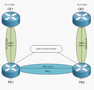 Ok, now it is time for some L2VPN. Here we will use the same diagram as before, but instead of providing MPLS VPN between CE1 and CE2, we are going to create a L2VPN so that CE1 and CE2 think that they are directly connected to each other.
First up, CE1
CE1(config-if)#int f0/0
CE1(config-if)#ip add 10.1.34.3 255.255.255.0
CE1(config-if)#int l0
CE1(config-if)#ip add 10.1.3.3 255.255.255.255
CE1(config-if)#router ospf 1
CE1(config-router)#net 10.0.0.0 0.255.255.255 a 0
CE1(config-router)#
Now CE2
CE2(config-if)#ip add 10.1.34.4 255.255.255.0
CE2(config-if)#int l0
CE2(config-if)#ip add 10.4.4.4 255.255.255.255
CE2(config-if)#router ospf 1
CE2(config-router)#net 10.0.0.0 0.255.255.255 a 0
CE2(config-router)#
Ok, now time for the PE routers. PE1:
First, lets reset the interface to all its defaults:
RP/0/RSP0/CPU0:PE1(config)#default interface g0/1/0/19
RP/0/RSP0/CPU0:PE1(config)#commit
Now PE2:
RP/0/RSP0/CPU0:PE2(config)#default interface g0/1/0/19
RP/0/RSP0/CPU0:PE2(config)#commit
Now, lets kill our OSPF sessions. On both routers: PE1:
RP/0/RSP0/CPU0:PE1(config)#no router ospf 100
RP/0/RSP0/CPU0:PE1(config)#commit
PE2:
RP/0/RSP0/CPU0:PE2(config)#no router ospf 100
RP/0/RSP0/CPU0:PE2(config)#commit
OK, now we can build out L2VPN cross-connects.
Fist up, we need to get to the L2VPN configuration
 RP/0/RSP0/CPU0:PE1(config)#l2vpn
Now to configure our X-Connect group
RP/0/RSP0/CPU0:PE1(config-l2vpn)#xconnect group R3R4
And our Point-to-Point settings
RP/0/RSP0/CPU0:PE1(config-l2vpn-xc)#p2p R3_to_R4
Place the interface in the P2P group R3_to_R4
RP/0/RSP0/CPU0:PE1(config-l2vpn-xc-p2p)#interface g0/1/0/19
Specify our Neighbor for this with a pseudowire ID (think of it as a circuit
ID) and then commit our changes
RP/0/RSP0/CPU0:PE1(config-l2vpn-xc-p2p)#neighbor 150.2.2.2 pw-id 304
RP/0/RSP0/CPU0:PE1(config-l2vpn-xc-p2p-pw)#comm
Now, this is unique to our CE devices, we need to specify the speed in order to get the interfaces up as the CE routers here do not support Gigabit Ethernet
RP/0/RSP0/CPU0:PE2(config-if)#int g0/1/0/19
RP/0/RSP0/CPU0:PE2(config-if)#spee 100
RP/0/RSP0/CPU0:PE2(config-if)#comm
Now for PE2:
RP/0/RSP0/CPU0:PE2(config)#l2vpn
RP/0/RSP0/CPU0:PE2(config-l2vpn)#xconnect group R3R4
RP/0/RSP0/CPU0:PE2(config-l2vpn-xc)#p2p R3_to_R4
RP/0/RSP0/CPU0:PE2(config-l2vpn-xc-p2p)#interface g0/1/0/19
The Pseudo-wire ID must match.
RP/0/RSP0/CPU0:PE2(config-l2vpn-xc-p2p)#neighbor 150.1.1.1 pw-id 304
RP/0/RSP0/CPU0:PE2(config-l2vpn-xc-p2p-pw)#comm
RP/0/RSP0/CPU0:PE2(config-if)#int g0/1/0/19
RP/0/RSP0/CPU0:PE2(config-if)#spee 100
RP/0/RSP0/CPU0:PE2(config-if)#comm
Now we can look at our L2VPN Cross-connects
RP/0/RSP0/CPU0:PE1#sh l2vpn xconnect
Tue Apr 24 03:40:36.619 UTC
Legend: ST = State, UP = Up, DN = Down, AD = Admin Down, UR = Unresolved, SB = Standby, SR = Standby Ready
XConnect Segment 1 Segment 2
Group Name ST Description ST Description ST
——————— —————— ————————- R3R4 R3_to_R4 UP Gi0/1/0/19 UP 150.2.2.2 304 UP
 ———————————————————————-
RP/0/RSP0/CPU0:PE1#
There you go, that looks good. Now, can we PING between CE1 and CE2? CE1#p 10.1.34.4
Type escape sequence to abort.
Sending 5, 100-byte ICMP Echos to 10.1.34.4, timeout is 2 seconds:
!!!!!
Success rate is 100 percent (5/5), round-trip min/avg/max = 1/1/4 ms
Yup, PING works. Hmm, wonder what CDP looks like? CE1#sh cdp nei
Capability Codes: R – Router, T – Trans Bridge, B – Source Route Bridge
S – Switch, H – Host, I – IGMP, r – Repeater
|
Device |
ID |
Local Intrfce |
Holdtme |
Capability |
Platform |
Port ID |
|
CE2 |
Fas 0/0 |
160 |
R S I |
2811 |
Fas 0/0 |
|
|
CE1# |
Now if we look at OSPF: CE1#sh ip ospf neighbor
Neighbor ID Pri State Dead Time Address Interface
 10.4.4.4 1 FULL/DR 00:00:33 10.1.34.4 FastEthernet0/0
All neighbored up! That means we should be able to PING between loopback interfaces:
CE1#p 10.4.4.4 so l0
Type escape sequence to abort.
Sending 5, 100-byte ICMP Echos to 10.4.4.4, timeout is 2 seconds:
Packet sent with a source address of 10.1.3.3
!!!!!
Success rate is 100 percent (5/5), round-trip min/avg/max = 1/1/4 ms
CE1#
 24.NHRP ( HSRP & VRRP)
Next Hop Resolution Protocol comes in two fashions on the IOS XR. The first is Cisco proprietary and called Hot-Standby Router Protocol or HSRP and the other is the industry standard called Virtual Router Redundancy protocol or VRRP.
This is something that many customers use in order to maintain the availability of a default gateway on the network. If your customer uses a static route to a next hop, you might be using this as well.
Like everything else with IOS XR, NHRP is handled a little differently. With IOS, you configure your standby commands under the interfaces; in IOS XR you use ROUTER HSRP or Router VRRP.
For this lab we will use interface Te0/1/0/0 and a subnet of 150.1.12.0/24. First up R1:
RP/0/RSP0/CPU0:R1(config)#int tenGigE 0/1/0/0
RP/0/RSP0/CPU0:R1(config-if)#ip add 150.1.12.1/24
RP/0/RSP0/CPU0:R1(config-if)#no shut RP/0/RSP0/CPU0:R1(config-if)#commit RP/0/RSP0/CPU0:R1(config-if)#
Now R2:
RP/0/RSP0/CPU0:R2(config)#int tenGigE 0/1/0/0
RP/0/RSP0/CPU0:R2(config-if)#ip add 150.1.12.2/24
RP/0/RSP0/CPU0:R2(config-if)#no shut
RP/0/RSP0/CPU0:R2(config-if)#commit
Now we should test PING from R1 to R2: RP/0/RSP0/CPU0:R1#ping 150.1.12.2
Type escape sequence to abort.
Sending 5, 100-byte ICMP Echos to 150.1.12.2, timeout is 2 seconds:
!!!!!
Success rate is 100 percent (5/5), round-trip min/avg/max = 1/1/2 ms
RP/0/RSP0/CPU0:R1#
Good, we have connectivity.
HSRP is up first!
First thing, from config mode, enter router hsrp
RP/0/RSP0/CPU0:R1(config)#router hsrp
Now we tell it what interface we are configuring HSRP under
RP/0/RSP0/CPU0:R1(config-hsrp)#interface tenGigE 0/1/0/0
And then we configure our HSRP ID and associated information. Instead of using the standby command, we are using the HSRP command. RP/0/RSP0/CPU0:R1(config-hsrp-if)#hsrp 100 ipv4 150.1.12.100
RP/0/RSP0/CPU0:R1(config-hsrp-if)#hsrp 100 priority 150
RP/0/RSP0/CPU0:R1(config-hsrp-if)#hsrp 100 preempt
RP/0/RSP0/CPU0:R1(config-hsrp-if)#hsrp 100 authentication cisco
RP/0/RSP0/CPU0:R1(config-hsrp-if)#exit RP/0/RSP0/CPU0:R1(config-hsrp)#exit RP/0/RSP0/CPU0:R1(config)#exit
And save your changes!
Uncommitted changes found, commit them before exiting(yes/no/cancel)? [cancel]:yes
Ok, now to configure R2
RP/0/RSP0/CPU0:R2(config)#router hsrp
RP/0/RSP0/CPU0:R2(config-hsrp)#interface tenGigE 0/1/0/0
RP/0/RSP0/CPU0:R2(config-hsrp-if)#hsrp 100 ipv4 150.1.12.100
RP/0/RSP0/CPU0:R2(config-hsrp-if)#hsrp preempt RP/0/RSP0/CPU0:R2(config-hsrp-if)#hsrp authentication cisco RP/0/RSP0/CPU0:R2(config-hsrp-if)#comm
Back to R1 to validate HSRP RP/0/RSP0/CPU0:R1#sh hsrp
P indicates configured to preempt.
|
Interface Grp Pri P State Active addr Standby addr Group addr
Te0/1/0/0 100 150 P Active local 150.1.12.2 150.1.12.100
RP/0/RSP0/CPU0:R1#
There we go, we now have HSRP on R1 active with R2 as standby.
Time for some VRRP
One thing cool about VRRP, you don’t have to burn an IP address just for the virtual. You can use an actual physical IP address of a router. If that router goes off-line, then the other router will just assume the IP address.
R1 up first, and we will use the R1 Te0/1/0/0 IP address for the virtual. First though, we need to remove HSRP and save the changes. RP/0/RSP0/CPU0:R1(config)#no router hsrp
RP/0/RSP0/CPU0:R1(config)#commit
Ok, to configure VRRP the command is router vrrp
RP/0/RSP0/CPU0:R1(config)#router vrrp
Again, then you tell it what interface
RP/0/RSP0/CPU0:R1(config-vrrp)#interface tenGigE 0/1/0/0
Since VRRP likes IPV6, we need to use the address-family command
RP/0/RSP0/CPU0:R1(config-vrrp-if)#address-family ipv4
Then configure our VRRP ID
RP/0/RSP0/CPU0:R1(config-vrrp-address-family)#vrrp 1
Assign the IP, here I am using the same IP as our physical interface
RP/0/RSP0/CPU0:R1(config-vrrp-virtual-router)#address 150.1.12.1
 RP/0/RSP0/CPU0:R1(config-vrrp-virtual-router)#text-authentication cisco RP/0/RSP0/CPU0:R1(config-vrrp-virtual-router)#commit RP/0/RSP0/CPU0:R2(config-vrrp-virtual-router)#
Now for R2, but this time we will decrease the priority so that R1 is the active router
RP/0/RSP0/CPU0:R2(config)#no router hsrp RP/0/RSP0/CPU0:R2(config)#commit RP/0/RSP0/CPU0:R2(config)#router vrrp RP/0/RSP0/CPU0:R2(config-vrrp)#interface tenGigE 0/1/0/0
RP/0/RSP0/CPU0:R2(config-vrrp-if)#address-family ipv4
RP/0/RSP0/CPU0:R2(config-vrrp-address-family)#vrrp 1
RP/0/RSP0/CPU0:R2(config-vrrp-virtual-router)#address 150.1.12.1
RP/0/RSP0/CPU0:R2(config-vrrp-virtual-router)#text-authentication cisco
RP/0/RSP0/CPU0:R2(config-vrrp-virtual-router)#priority 50
RP/0/RSP0/CPU0:R2(config-vrrp-virtual-router)#commit RP/0/RSP0/CPU0:R2(config-vrrp-virtual-router)# RP/0/RSP0/CPU0:R2#
Now back to R1 to see the VRRP status: RP/0/RSP0/CPU0:R1#show vrrp
IPv4 Virtual Routers:
A indicates IP address owner
| P indicates configured to preempt
| |
Interface vrID Prio A P State Master addr VRouter addr
Te0/1/0/0 1 255 A P Master local 150.1.12.1
IPv6 Virtual Routers:
A indicates IP address owner
| P indicates configured to preempt
| |
Interface vrID Prio A P State Master addr VRouter addr
RP/0/RSP0/CPU0:R1#
Nice, R1 is the MASTER. Wonder what R2 says? RP/0/RSP0/CPU0:R2#sh vrrp
IPv4 Virtual Routers:
A indicates IP address owner
| P indicates configured to preempt
| |
Interface vrID Prio A P State Master addr VRouter addr
Te0/1/0/0 1 50 P Backup 150.1.12.1 150.1.12.1
IPv6 Virtual Routers:
A indicates IP address owner
| P indicates configured to preempt
 | |
| |
Interface vrID Prio A P State Master addr VRouter addr
RP/0/RSP0/CPU0:R2#
It says it’s the backup! Nice.
This page intentionally left black for notes.
IPv6 Multihoming
Aside
IPv6 Multihoming
IPv6 Multihoming (Part 1 PI,PA and , Metro Addresss)
.. IPv6 does not have a set solution to the problem
.. IETF Working Group
.. multi6 WG
.. Activity in this group has been low
.. There have been over 40 Drafts proposed in the last five
years or so, but almost universally failed to reach RFC status
.. shim6 (Site Multihoming by IPv6 Intermediation) WG
.. Based on the architecture developed by IETF multi6 working group
.. Focus on IPv6-based site multi-homing solution that inserts a new sub-layer (shim) into the IP stack of end-system hosts
.. Locater-identifier approach looks likely to be adopted as a longer-term solution
Categories of Possible Approaches
- PI (Provider Independent) Addressing
End sites obtain IP address space independently from the providers
to which it is attached
These addresses might not be globally routable.
The solution may not scale to Internets
Notes
IPv6 為防止網際網路上的routing entries過多,目前
尚未開放End Sites使用PI addresses。
ARIN、RIPE及APNIC 都已有IPv6 PI Address Draft Policy提出討論,以暫時因應
用戶可能之需求及 IPv6推展之需要。
詳情請參考 TWNIC 6th OPM資料
-
PA (Provider Aggregatable) Addressing
End User轉到新Service Provider時,必須歸還給原 Service Provider
Using one ISP’s PA with a different ISP
Issues of ingress filtering
Deploy multiple prefixes delegated by ISPs
Possible Approaches
Routing
Mobility
New Protocol Element
Modify a Protocol Element
Modified Site-Exit Router interaction
-
Metro Addressing
An address prefix is assigned to a
suitable regional authority such as acity
The authority :
Assigns small (/64, /60, /56) prefixes to
smaller entities in
the region
Obtains agreements from the ISPs to use
those prefixes for their
multihomed
customers and route among themselves for
other customers
Only the larger prefix is advertised outside
the region
Possible implementation
All the ISPs maintain bilateral contracts and exchange
more specific route with each other, or
All of the ISPs contract with a routing exchange point
operated by the regional authority
In Metro model, traffic is carried by sender’s ISP
to the region and transits to the destination ISP
There is an implied transit model that has to be accounted
for
New ISP buys transit from all others?
Some form of transit cost settlements between ISPs?
CCK調變
圖庫
Ospf LSA 類型
回應
Ospf LSA 類型:
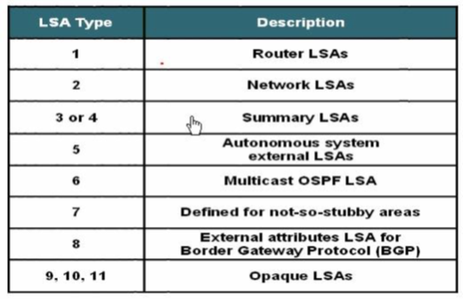
研究LSA 主要看LSA 的下面3 個方面:
1.
傳播範圍
2.
通告者
3.
內容
Show ip ospf database 可以看見簡略的database 資訊,
Show ip ospf database 後接不通的命令可以看見不同類型LSA 的詳細資訊。
如下圖:
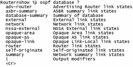
1 類Router LSA
One router LSA (type 1) for every router in an area
Includes list of directly attached links
Each link identified by IP prefix assigned to link and link type
Identified by the router ID of the originating router
Floods within its area only; does not cross ABR
***傳播區域:只能在本區域,及不能通過ABR
***通告者:
每台路由器都可以產生1 類LSA
***內容:含有拓撲信息和直連的路由
R1 # show ip ospf database 可以看見一下簡略資訊
Router Link States (Area 0)
Link ID ADV Router Age Seq# Checksum Link count
11.1.1.1 11.1.1.1 1546 0x80000007 0x00FF34 3
22.2.2.2 22.2.2.2 1530 0x80000008 0x00FF20 3
其中link ID 和ADV Router 都是此LSA 的router id 。
在相同區域內1 類LSA 的內容相同。
R1 # show ip ospf database router 可以看見1 類LSA 的詳細資訊
OSPF Router with ID (11.1.1.1) (Process ID 1)
Router Link States (Area 0)
LS age: 793
Options: (No TOS-capability, DC)
LS Type: Router Links
Link State ID: 11.1.1.1
Advertising Router: 11.1.1.1
LS Seq Number: 80000007
Checksum: 0xFF34
Length: 60
Number of Links: 3
Link connected to: a Stub Network
(Link ID) Network/subnet number: 1.1.1.1
(Link Data) Network Mask: 255.255.255.255
Number of TOS metrics: 0
TOS 0 Metrics: 1 (這塊為直連路由信息)
Link connected to: another Router (point-to-point)
(Link ID) Neighboring Router ID: 22.2.2.2
(Link Data) Router Interface address: 12.1.1.1
Number of TOS metrics: 0
TOS 0 Metrics: 64 (這塊為直連拓撲信息)
Link connected to: a Stub Network
(Link ID) Network/subnet number: 12.1.1.0
(Link Data) Network Mask: 255.255.255.0
Number of TOS metrics: 0
TOS 0 Metrics: 64 (這塊為直連路由信息)
詳細LSA 資訊過長省略部分。
2 類Network LSA
One network (type 2) LSA for each transit broadcast or NBMA network
In an area
Includes list of attached routers on the transit link
Includes subnet mask of link
Advertised by the DR of the broadcast network
Floods within its area only; does not cross ABR
***傳播區域:只能在本區域,及不能通過ABR
***通告者:
DR 產生2 類LSA
***內容:在這個MA 網路中附屬的路由器和遮罩。
R # show ip ospf database 可以看見一下簡略資訊
Net Link States (Area 0)
Link ID ADV Router Age Seq# Checksum
192.168.1.3 33.3.3.3 349 0x80000001 0x00D586
其中Link ID 為DR 的藉口位址ADVR 為DR 的
Router ID 。
R # show ip ospf database network 可以看見2 類的詳細資訊
OSPF Router with ID (22.2.2.2) (Process ID 1)
Net Link States (Area 0)
Routing Bit Set on this LSA
LS age: 879
Options: (No TOS-capability, DC)
LS Type: Network Links
Link State ID: 192.168.1.3 (address of Designated Router)
Advertising Router: 33.3.3.3 (DR’ router id)
LS Seq Number: 80000001
Checksum: 0xD586
Length: 32
Network Mask: /24
Attached Router: 33.3.3.3 (在MA 網路中的路由器router id )
Attached Router: 22.2.2.2 (在MA 網路中的路由器router id )
3 類summary LSA
Type 3 LSAs are used to flood network information to areas outside the
originating area (interarea)
Describes network number and mask of link.
Advertised by the ABR of originating area.
Regenerated by subsequent ABRs to flood throughout the autonomous system.
By default, routes are not summarized, and type 3 LSA is advertised for every subnet.
***傳播區域:整個OSPF 域
***通告者:
ABR 產生3 類LSA
***內容:傳播域間路由
R # show ip ospf database 信息
Summary Net Link States (Area 2)
Link ID ADV Router Age Seq# Checksum
1.1.1.1 33.3.3.3 1365 0x80000001 0x008844
2.2.2.2 33.3.3.3 1365 0x80000001 0x00D731
3.3.3.3 33.3.3.3 36 0x80000001 0x009F66
12.1.1.0 33.3.3.3 1365 0x80000001 0x00F8CA
192.168.1.0 33.3.3.3 1365 0x80000001 0x006D3A
其中link id 為區域的路由資訊,ADV Router 為ABR的Router
ID。
Router # show ip ospf database summary 信息
Summary Net Link States (Area 1)
Routing Bit Set on this LSA
LS age: 1521
Options: (No TOS-capability, DC, Upward)
LS Type: Summary Links (Network)
Link State ID: 2.2.2.2 (summary Network Number)
Advertising Router: 22.2.2.2 (ABR Router’ ID )
LS Seq Number: 80000002
Checksum: 0x44D2
Length: 28
Network Mask: /32
TOS: 0 Metric: 1
Routing Bit Set on this LSA
LS age: 656
Options: (No TOS-capability, DC, Upward)
LS Type: Summary Links(Network)
Link State ID: 3.3.3.3 (summary Network Number)
Advertising Router: 22.2.2.2
LS Seq Number: 80000001
Checksum: 0x22F0
Length: 28
Network Mask: /32
TOS: 0 Metric: 2
5 類External LSA
External (type 5) LSAs are used to advertise networks from other
autonomous systems.
Type 5 LSAs are advertised and owned by the originating ASBR.
Type 5 LSAs flood throughout the entire autonomous system.
The advertising router ID (ASBR) is unchanged throughout the autonomous system.
Type 4 LSA is needed to find the ASBR.
By default, routes are not summarized
***傳播區域:整個OSPF 域
***通告者:
ASBR
***內容:域外路由
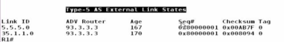
其中5 類的ADV Router 為ASBR 的Router ID
Link ID 為:域外的路由
4 類Summary LSA
Summary (type 4) LSAs are used to advertise an ASBR to all other areas in
the autonomous system.
They are generated by the ABR of the originating area.
They are regenerated by all subsequent ABRs to flood throughout the
autonomous system.
Type 4 LSAs contain the router ID of the ASBR.
***傳播區域:除過ASBR 在的區域的整個OSPF 域(因為1
類LSA 已經告訴了ASBR 在那)
***通告者:
ABR 及在那個區域就是那個區域的ABR
***內容:找ASBR
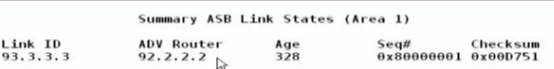
其中Link ID 為ASBR 的Router ID
ADV Router 為路由器所在區域的ABR 的Router ID
總結:
其中1 ,3 ,
5 類LSA 為路由信息。
1 類為域內路由 (O) Derive from LSA 1,LSA2
2 類為跨域路由 (OIA) Derive from LSA 3
3 類為外部路由 (OEx) Derive from LSA 5
(If NSSA Area (ONx) derive from LSA7
ROUTE-LAB
ROUTE-LAB
LAB 1-1
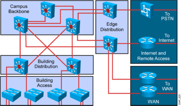
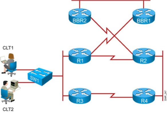
目的:
- 確認必須提供的網路需求
- 確認必須的訊息
- 確認實行時需要的工作及建立實施計劃
- 驗證活動
實施政策
- 基礎結構採用 CISCO 的三層式架構:
-
必須滿足的基本要求
- Functionality 在時限內滿足並且支援應用程式及資料流量的需
- Performance 滿足企業對 響應速度,吞吐量,利用率
- Scalability 滿足企業對 人員,應用程式及資料流量未來的可擴展性
- Availability 提供企業網路及應用接近 99.999的可用性
- Cost-effectiveness: 在限定的預算
- Functionality 在時限內滿足並且支援應用程式及資料流量的需
解決方案範例.
- 1-確認必須提供的網路需求& 2. 確認必須的訊息
1.1 使用的應用程式及需要的資料流量
1.2 存在的網路設備,及其作業系統/固件(OS /FirmWare)
1.3 拓樸圖及連線資訊
1.4 IP位址及部署分配
1.5 使用的路由協定及路由器上的設定(注:通常應為所有的網路設備協定)
- 3-確認實行時需要的工作及建立實施計劃
2.1 撰寫必要交件的資訊
2.2 準備必須的工具及資源
連接PC(Terminal)到設備
選擇並且保留必要資源
2.3 設定所有設備上的IP位址
2.4 啟用所有參與運作的界面
2.5 設定網路設備上的必要協定(例:路由協定 )
2.6 設定特定網路設備上的必要特性(例:路由聚合,及封閉網路)
2.7 驗證網路設備及連線是否依據設定正常的運作
2.8 測量執行效率及記錄結果是否滿足
2.9 建立設定備份
2.10建立實施計劃,網路維運基線,及提出必要建議
- 4-驗證活動
3.1 驗證所有設備界面正常運作
3.2 驗證網路設備上的設定是否正運作(例:路由協定)
3.3 驗證網路設備上的路徑是否正確(例:路由表是否包含所有規劃的正確路徑)
3.4 驗證特定網路設備上的必要特性(例:送出聚合路由的路由器是否自我生成指向null0界面的路)
3.5 驗證網路設備上的路徑是否正確及是否要進行調整
LAB 2-1
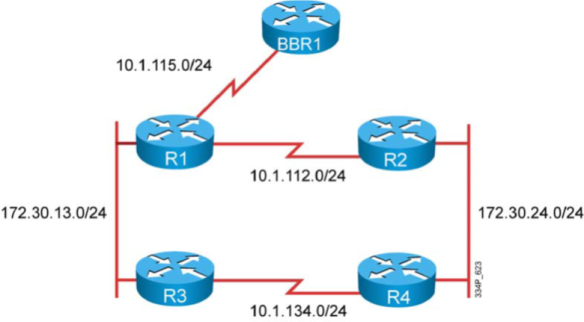
目的:
- 在WAN 和 LAB 的界面上設定基本的EIGRP及驗證其運
- 使用必要的工具及指令進行設定
- 在某一路由器上使用LAN界面上的次要IP位址加入EIGRP路由協定
- 更改EIGRP路徑測量參數來影響路由的選擇
- 最佳化-1.避免EIGRP的界面送出不必要的HELLO封包訊息
- 最佳化-2.避免不必要的小路由被送出,在特定設備上執行路由聚合
- 列出實施行步驟
- 寫下驗證,測試的計劃檢查所有的設定如規劃方式進行運作
- 利用 SHOW 及 DEBUG的指令檢查設定及驗證運作
以上router的介面名稱可能與您正在使用的Lab有所不同, 請以實際介面名稱為準.
1 講師已為您準備好基本設定 (IP, Frame-Relay Map)
2 啟動EIGRP 於:
2.1 R1-BBR1 的p2p sub-interface 介面
2.2 R1-BBR2 的p2p sub-interface 介面
2.3 R3-R4 的 p2p sub-interface 介面, 含 LAN 的網段.
2.4 EIGRP 的設定應讓這個Lab所使用的其它子網路一但加入時, 會自動加到 EIGRP 的 Table 中.
3 確定 R1 的 Topology Table 與 Routing Table:
3.1 由 BBR1 學到 192.168.x.0/24
3.2 由 BBR2 學到 172.30.10.0/24
3.3 比對 Topology Table 與 Routing Table 中的Metric 值.
4 啟動 EIGRP 於:
4.1 R1 與 (R2, R3, R4) 間的 Multipoint Sub-interface.
4.2 所有Router 要能交換 Routes.
5 檢查 Neighbor 與 Routing Table:
5.1 R1-R2
5.2 R1-R3
5.3 R1-R4
5.4 Shutdown R3-R4, 檢查 R3此時學不到 172.30.24.0/24
6 調整 R1 的設定:
6.1 讓 R3 與 R4 仍能學到彼此的LAN subnet.
6.2 No shutdown R3-R4 間的介面.
7 檢查 R1-R2, R1-R3, R1-R4:
7.1 Neighbor Table
7.2 Topology Table
7.3 Routing Table
7.4 觀察 Topology Table 與 Routing Table 的 metric 變化.
7.5 再次 shutdown R3-R4 間的介面, 並確認 R2, R4 是從 R1 學到 172.30.13.0/24
8 正確調整參數, 影響路徑的選擇:
8.1 設定R3 與 R4之間介面的 Delay, 讓R2把學自R1的Route當作是Feasible Successor(Backup)
8.2 設定 R3, 讓R3到 172.30.24.0/24 的路徑可執行 Unequal Cost Load Balancing.
8.3 設定正確Route與參數, 讓 R3 到 172.30.24.0/24 的路徑是以 R4作為 Primary Route, 以 R1作為Backup Route.
9 最後, 確定要讓R3的 LAN 要能與 R2, R4 的 LAN 仍然可以建立連線.
Sol:
LAB2-2

以上router的介面名稱可能與您正在使用的Lab有所不同, 請以實際介面名稱為準.
1 講師已為您準備好基本設定 (IP, Frame-Relay Map)
2 啟動EIGRP 於:
2.1 R1-BBR1 的p2p sub-interface 介面
2.2 R1-BBR2 的p2p sub-interface 介面
2.3 R3-R4 的 p2p sub-interface 介面, 含 LAN 的網段.
2.4 EIGRP 的設定應讓這個Lab所使用的其它子網路一但加入時, 會自動加到 EIGRP 的 Table 中.
3 確定 R1 的 Topology Table 與 Routing Table:
3.1 由 BBR1 學到 192.168.x.0/24
3.2 由 BBR2 學到 172.30.10.0/24
3.3 比對 Topology Table 與 Routing Table 中的Metric 值.
4 啟動 EIGRP 於:
4.1 R1 與 (R2, R3, R4) 間的 Multipoint Sub-interface.
4.2 所有Router 要能交換 Routes.
5 檢查 Neighbor 與 Routing Table:
5.1 R1-R2
5.2 R1-R3
5.3 R1-R4
5.4 Shutdown R3-R4, 檢查 R3此時學不到 172.30.24.0/24
6 調整 R1 的設定:
Sol:
LAB 2-3

以上router的介面名稱可能與您正在使用的Lab有所不同, 請以實際介面名稱為準.
1 在LAN介面上設定EIGRP Authentication.
1.1 EIGRP Authentication 應使用 安全的機制.
1.2 EIGRP Authentication 的密碼永不過期.
1.3 在所有Router上應用正確的指令檢查 Key Chain 的設定正確無誤, 並且使用正確的key 在作Authentication, 確認 Key 的時間永不過期.
1.4 檢查 EIGRP Neighbor 正確的建立.
1.5 檢查 EIGRP Routing 都有正確學習到每一個Router上.
2 在WAN介面上設定 EIGRP Authentication.
2.1 EIGRP Authentication 應使用 安全的機制.
2.2 EIGRP Authentication 的密碼永不過期.
2.3 在所有Router上應用正確的指令檢查 Key Chain 的設定正確無誤, 並且使用正確的key 在作Authentication, 確認 Key 的時間永不過期.
2.4 檢查 EIGRP Neighbor 正確的建立.
2.5 檢查 EIGRP Routing 都有正確學習到每一個Router上.
6.1 讓 R3 與 R4 仍能學到彼此的LAN subnet.
6.2 No shutdown R3-R4 間的介面.
7 檢查 R1-R2, R1-R3, R1-R4:
7.1 Neighbor Table
7.2 Topology Table
7.3 Routing Table
7.4 觀察 Topology Table 與 Routing Table 的 metric 變化.
7.5 再次 shutdown R3-R4 間的介面, 並確認 R2, R4 是從 R1 學到 172.30.13.0/24
8 正確調整參數, 影響路徑的選擇:
8.1 設定R3 與 R4之間介面的 Delay, 讓R2把學自R1的Route當作是Feasible Successor(Backup)
8.2 設定 R3, 讓R3到 172.30.24.0/24 的路徑可執行 Unequal Cost Load Balancing.
8.3 設定正確Route與參數, 讓 R3 到 172.30.24.0/24 的路徑是以 R4作為 Primary Route, 以 R1作為Backup Route.
9 最後, 確定要讓R3的 LAN 要能與 R2, R4 的 LAN 仍然可以建立連線
Sol:
LAB2-4
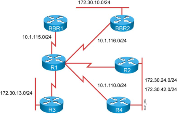
Trouble Ticket A: EIGRP Adjacency Issues
1 您已離開公司一段時間, 在這段時間當中, 有位資淺的工程師替代了您的工作. 由於當時正好有需求要新增額外的 IP 網段於R2與R4之間, 於是那位工程師便設定了額外的 IP網段, 但卻導致在此網段之外的其它網路因而斷線. 你被要求要檢查並更正這個錯誤, 以便讓此新增的網段能夠被存取及使用.
2 另一個問題是有關與BBR1 Router間的 EIGRP Adjacency, 就在你不在的這段時間, 這位資淺的工程師被要求改善與BBR1之間的Routing的安全性, 但是卻導致與BBR1無法建立Adjacency. 你再次被要求更正這個現象.
3 這位工程師也被要求要對EIGRP進行最佳化. 他作了一些設定以便改善R4的Metric計算的數值, 但此舉卻造成與R4之間斷線. 此外, 他企圖在 Routers上用summarization 的設定將Routing進行最佳化, 但卻沒有得到預期的結果, 你也被要求對此進行處理.
4 你的助手向你報告, 連接在R2與R4之間的LAN, 在最近才部署上去的R3上面是看不到的. R3僅有有限的連線. 但在R1上卻可以看到並存取所有的網路. 你必需找出問題並且對其進行更正.
Instructions:
5 你與同伴必需建立 Troubleshooting 與 Verification Plan 並進行分工. Trouble Ticket A 與 B是可以同步進行的. 請將處理的過程記錄於書上的"Troubleshooting Log"以便你能夠據此與同伴進行討論, 並且review整個過程.
Sol:
———————————————————————————————————————-
LAB3-1

1 設定OSPF於介面上 (R1-R3的LAN, R2-R4的LAN):
1.1 設定OSPF LAN的網段能夠被存取的到.
1.2 所有的Router都在Backbone Area.
1.3 OSPF 的設定應該要精確, 以免當額外的子網段介面加入時自動的啟動了OSPF.
1.4 IP Routing Table 中的網段也應該與實際網路遮罩吻合.
2 確認R1-R3, R2-R4的LAN
2.1 OSPF Neighbor已建立:
2.2 並檢查Neighbor建立的時間有多久?
2.3 是否有任何問題影響Neighbor的溝通? 例如封包在Queue中無法送出?
2.4 在不看Routing Table 與 Topology Table的情況下, 請確定有送出所有LAN與Loopback正確的Route以及正確的 Subnet mask.
2.5 檢查R1的Topology 與 Routing Table進行比較, 你應該看到R3的 Loopback網段及其metric 值.
2.6 確定R1與R3的LAN上是由 R1擔任DR.
Verify By # show ip ospf neighbor
3 設定OSPF於WAN介面上(R3-R4)
3.1 R3-R4需交換LAN與Loopback網段.
已經於 1 中完成
3.2 OSPF的設定是在 Frame-Relay的Point-to-Point介面上.
3.3 Area 請設定在Backbone Area之內.
3.4 OSPF的設定應該要精確, 以便有額外的IP加入Router時不會自動的被加入OSPF送出.
Verify By #show ip ospf neighbor
4 確認R3-R4的WAN
4.1 OSPF Neighbor已建立:
4.2 並檢查Neighbor建立的時間有多久?
4.3 是否有任何問題影響Neighbor的溝通? 例如封包在Queue中無法送出?
4.4 在不看Routing Table 與 Topology Table的情況下, 請確定有送出所有LAN與Loopback正確的Route以及正確的 Subnet mask.
4.5 檢查R1的Topology 與 Routing Table進行比較, 你應該看到R3的 Loopback網段及其metric 值.
Verify by
1. sh ip protocols
2. Sh ip ospf database
3. Sh ip route
5 設定OSPF於WAN介面上(R1-R2, R1-R4)
5.1 OSPF的設定是在 Frame-Relay的Multi-point介面上.
5.2 Area 請設定在Backbone Area之內.
5.3 OSPF的設定應該要精確, 以便有額外的IP加入Router時不會自動的被加入OSPF送出.
Note: multi-point subinterface require Neighbor Command config on one of multipoint interface connected router
6 確認R1-R2, R1-R4的WAN
6.1 OSPF Neighbor已建立:
6.2 並檢查Neighbor建立的時間有多久?
6.3 是否有任何問題影響Neighbor的溝通? 例如封包在Queue中無法送出?
6.4 檢查所有的Router的Topology Table與Routing Table都有學習到所有的Routes及正確的Subnet Mask.
Sol:
R1
Config T
Router OSPF 1
Network 10.1.1.1 0.0.0.0 area 0
Network 172.30.13.0 0.0.0.255 area 0
Network 10.1.110.0 0.0.0.255 area 0
R2
Config T
Router OSPF 1
Network 10.2.2.2 0.0.0.0 area 0
Network 172.30.24.0 0.0.0.255 area 0
Network 10.1.110.0 0.0.0.255 area 0
R3
R4
Config T
Router OSPF 1
Network 10.4.4.4 0.0.0.0 area 0
Network 172.30.24.0 0.0.0.255 area 0
Network 10.1.110.0 0.0.0.255 area 0
Network 10.1.134.0 0.0.0.255 area0
——————————————————————————————————————————
LAB 3-2
–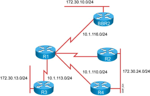
1 設定R1-BBR2 WAN 界面上OSPF於(R1-BBR2):
BBR2已經預設為Area 0.
啟動 OSPF 於 R1與BBR2的 WAN介面, 同樣是 Area0.
R1應該由BBR2收到172.30.10.0/24 的網段.
R1
Conf t
Router os 1
Network 10.1.116.0 0.0.0.255 area 0
End
Sh ip os n
Sh ip osp da
Sh ip ro
2 確認OSPF的設定(R1-BBR2):
Neighbor 應該已經建立
比對 R1的LSDB與IP Routing Table, 應正確學到Routes.
確定R1的Route可以與172.30.10.0/24網段連線.
3 設定其它OSPF Area (R2, R3, R4):
設定R3的所有介面於 Area 3之中.
設定R2與R4 的所有介面於Area24之中.
檢查所有的Router都應該學習到所有網段的Routes.
4 確認OSPF的設定:
R1與R3應建立Adjacency於Area 3之中.
比對R3的LSDB, Routing Table. R3應正確學到Routes.
R1-R2, R1-R4應建立Adjacency於Area 24之中.
比對R2與R4的LSDB, Routing Table.
R2, R4應正確學到Routes, 包含來自BBR2的subnets.
確定可以正確連到BBR2的172.30.10.0/24 Subnet.
5 調整OSPF參數:
請在Area24中精確的調整Path Cost, 影響運算的結果. 目的是讓R1的172.30.24.0/24 Route是以R2為最佳路徑.
為了讓Area 0更穩定, 請手動指定R1的Router ID.
請在R3上設定讓LAN網段減少不必要的Traffic. 目的是簡省CPU的運算.
6 確認OSPF的設定:
確定所有的Router的OSPF Adjacency 都是 up並且運作正常.
R1應與BBR2在 Area0 中.
R1應與R3在Area3 中.
R1應與R2, R4 在Area24中.
R1應使用新定的Router ID.
R1應使用R2作為前往172.30.24.0/24 做為最佳路徑.
R3應只有與R1建立Adjacency
R3不應透過LAN與R1建立Adjacency.
SOL
2. 檢測OSPF的基本設定,運作及目前網路的結構
Rl#show ip ospf neighbor
Rl#show ip ospf database
3. Summarizing the OSPF intemal routes.
R1#
router ospf 1
area 0 range 172.30.0.0 255.255.0.0
4. 1. Use the following example to configure router R3 in this lab:
R3#
router ospf 1
summary-address 192.168.0.0 255.255.0.0
4.2. Verify the OSPF link-state databases and IP routing tables.
R1#show ip ospf database
——————————————————————————————————————————-
LAB3-3

檢查OSPF (R1-R4)目前的Routes:
R1-R4 都已設定將直接連接的網段以OSPF送出.
R3 已將OSPF External Routes送往你的OSPF網路當中.
檢查OSPF(R1-R4)既有狀態:
檢視R1-R4的設定, 包括涵蓋的network, 啟動的介面, Adjacencies, LSDB與OSPF的Area.
確定R1-R4都可以連到(Ping) 其所學到的每一個網段.
查看Routing Table, 寫下目前的各Router送出的Routes.
設定OSPF Internal Routes 的 Summarization:
根據前面收集的資訊, 進行Routes Summarization的設定.
你需要將來自BBR2的 172.30.x.0/24 Routes進行Summary.
確認OSPF Summarization的設定:
確定 R1-R4的Adjacency仍然正常.
檢查 172.30.x.0/24 經過 Summary 之後的Routes 資訊存在於R1-R4的LSDB 與Routing Table中.
確定各Router都能連線到(Ping)172.30.x.0/24 的IP.
進一步設定OSPF External Routes 的 Summarization:
R3目前已將192.168.x.0/24 的Routes 以 Redistribute的方式送入OSPF之中, 由於R3是這些網段的唯一來源, 因此沒有必要讓其它Router一一學習到每一筆192.168.x.0的Route. 但是, 未來還有可能會有192.168.x.0/24的網段會加入R3.
請設定將192.168.x.0/24 的Routes 進行 Summarization.
確認OSPF Summarization的設定:
確定 R1-R4的Adjacency仍然正常.
檢查 192.168.x.0/24 Summary 之後的Route 資訊存在於R1-R4的LSDB 與Routing Table中.
確定各Router都能連線到(Ping)192.168.x.0/24 的IP.
Solution
Summarizing the OSPF intemal routes.
1. Use the following example to configure router Rl in this lab:
R1
router ospf 1
area 0 range 172.30.0.0 255.255.0.0
- 驗證 OSPF link-state databases and IP routing tables.
Rl#show ip ospf database
Summarizing OSPF extemal routes.
1. Use the following example to configure router R3 in this lab:
R3#
router ospf 1
summary-address 192.168.0.0 255.255.0.0
2. Verify the OSPF link-state databases and IP routing tables.
R1#show ip ospf database
————————————————————————————————————————–
LAB 3-4

檢查OSPF (R1-R4)目前的Routes及 網路結構
R1-R4 都已設定將直接連接的網段以OSPF送出.
R3 同時也已將OSPF External Routes送往你的OSPF網路當中.
檢查OSPF(R1-R4)既有狀態:
檢視R1-R4的設定, 包括所涵蓋的OSPF範圍, 啟動的介面, Adjacencies, LSDB與OSPF的Area.
確定R1-R4都可連接到OSPF送出的每一個網段.
查看Routing Table, 記錄目前的各Router送出的Routes與IP定址.
設定OSPF Area 24 的 Area Type:
在R2與R4沒有足夠的CPU與Memory來處理來大量Routing Information. 因此必需設法降低R2與R4上的OSPF Link-State Database大小來節省資源的使用.
確認OSPF的設定:
確認R1與 R2, R3, R4, BBR2都有建立 Adjacency.
確認 R2 與 R4之間有建立 Adjacency.
檢查 R1 與 R3的LSDB, 確定它們都有每一筆OSPF internal 與 external 資訊, 且都有將正確的最佳路徑置入Routing Table.
檢查 R2 與 R4的LSDB有變得較小, 因它們不再擁有每一筆來自External 的網段的資訊, 也就是那些被Redistributed 進入 OSPF的Routes.
確定即使 R2 與 R4 沒有每一筆資訊的細節, 但仍然可以與External Routes的網段連線.
設定 OSPF Area 24 的 Area Type:
在前一個步驟中, 雖然已降低了Area 24 的LSDB的資訊數量以節省R2, R4的資源使用, 但你發現它們仍然無法處理所有OSPF的資訊. 因此, 需要進一步降低OSPF的資訊數量, 可是還是要維持讓R2 與 R4可以連線到每一個網段.
確認OSPF 的設定:
確認R1與 R2, R3, R4, BBR2都有建立 Adjacency.
確認 R2 與 R4之間有建立 Adjacency.
檢查 R1 與 R3的LSDB, 確定它們都有每一筆細節的OSPF internal 與 external 資訊, 且都有將正確的最佳路徑置入Routing Table.
檢查 R2 與 R4的LSDB有變得比較小, 因為它們不再擁有每一筆來自Area 24 以外的網段的資訊, 換言之就是那些被Redistribute 進入 OSPF的Routes以及其它Area的Routes.
確定即使 R2 與 R4 沒有每一筆資訊的細節, 但仍然可以與External Routes的網段
與其它的Area連線.
設定 OSPF Area 3 的 Area Type:
此步驟中將透過設定降低 Area 3 內的資訊數量.
你發現R3沒有足夠的記憶體來儲存所有的OSPF IP Routing 資訊, 換言之, 無法儲存任何動態學到的Routing 資訊.
確認OSPF 的設定:
確認R1與 R2, R3, R4, BBR2都有建立 Adjacency.
確認 R2 與 R4之間有建立 Adjacency.
檢查 R1的LSDB, 確定它們都有每一筆細節的OSPF internal 與 external 資訊, 且都有將正確的最佳路徑置入Routing Table.
確定 R1 可以連接所有學習到的網段.
檢查 R2 與 R4有來自Area 24 internal的Route, 但沒有Area24以外的網段的資訊. 即便如此, R2與R4 仍可連接每一個網段.
檢查 R3的Database並確認其Size變小了, Database 應該有Area3內部的資訊及Redistribute進入Area 3 的資訊, 但沒有任何來自其它Area的資訊或從其它Area 進來的 External Route.
確定 R3 可以連線到每一個網段.
Solution
1.SKIP
2.
Rl#
router ospf 1
area 24 stub
R2#
router ospf 1
area 24 stub
R4#
router ospf 1
area 24 stub
3.
4.
Use the following examplc to configure routcr R 1 in this lab:
R1#
router ospf 1
area 24 stub no-summary
5.
6.
5.1. Use the following example to configure router R1 in this lab:
R1#
router ospf 1
area 3 nssa no-summary
R3#
router ospf 1
area 3 nssa
7.
—————————————————————————————————————————–
LAB 3-5
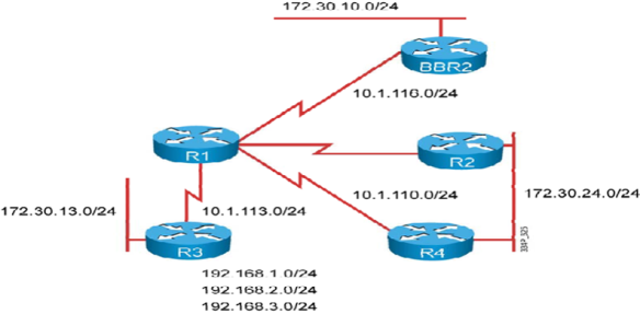
檢視網路目前的設定:
1 檢查Routing的設定與動作是否正常.
2 R1, R2, R3, R4目前應已設定OSPF並將它們直連的網段送出.
3 部份Router同時還送出一些External OSPF network 到OSPF的routing domain中.
網路管理員必需在Router上進行設定來防止Traffic被駭客侵入並製造Routing的黑洞, 因此:
1 請以per-interface設定OSPF Authentication於Area 3 與 Area24 的Router上.
2 於 R3-R1間使用Simple OSPF Authentication 並查看其動作過程.
3 於 R2-R4間的LAN使用較安全的 OSPF Authentication 並查看其動作過程.
由於使用最小的指令在下列OSPF AREA的所有界面設定較安全的 OSPF驗證:
1 在Area 24上設定Secure的OSPF Authentication驗證.
2 請確定Authentication成功, LSDB, Routing Table 學習正確.
SOLUTION
- 在所有的路由器上用下列指令記錄目前的 OSPF設定
Rx# show ip ospf
RX#show ip ospf databae
RX#show ip route [ospf ]
RX#show ip ospf neighbor
- 在 R1,R3 的OSPF 路由器上 ,針對WAN連結不同OSPF路由器的界面配置簡單密碼驗證 ,密碼為CISCO
在 R2,R4 的OSPF 路由器上 ,針對WAN連結不同OSPF路由器的界面配置較安全的md5驗證 ,ID及key為 1及CISCOR1#
interface SerialO/0/0.2 point-to-point
ip ospf authentication
ip ospf authentication-key CISCO
R2#
interface FastEthernetO/O
ip ospf authentication message-digest
ip ospf message-digest-key 1 md5 CISCO
R3#
interface SerialO/0/0.2 point-to-point
ip ospf authentication
ip ospf authentication-key CISCO
R4#
interface FastEthernetO/O
ip ospf authentication message-digest
ip ospf message-digest-key 1 md5 CISCO
-
驗證R1-R4在驗證後用
Rx# show ip ospf
RX#show ip ospf databae
RX#show ip route [ospf ]
RX#show ip ospf neighbor
令觀察的狀態和未驗證之前相同
LAB 4-1
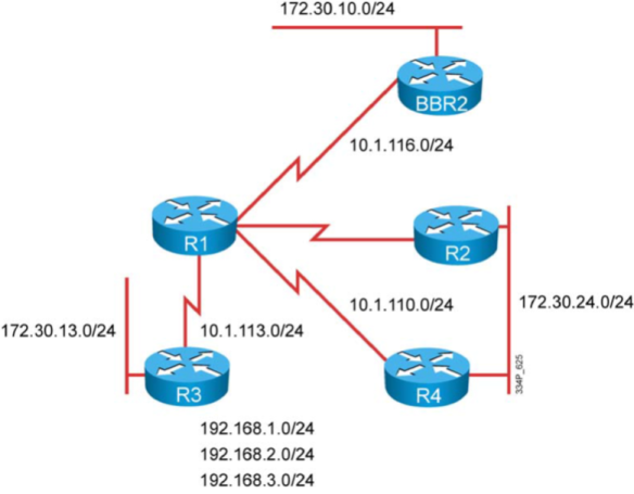
基本設定
- 在R1與R3之間設定RIPv2路由協定,並且宣告R3的區域網路網段,RIPv2只在廣域網路上交換更新訊息 .
- 在R1, R2 與 R4之間設定 OSPF.路由協定,R1的OSPF路由執行程序只包含連結到 R2,R4的廣域網路界面,
而R2,R4則除了連結R1的廣域網路亦包含了區域網路.
- 在R1 與 BBR2之設定EIGRP路由協定.
- 確認R1與R3之間的RIPv2已啟動, 且R1可以存取由RIPv2學到的網段.
- 確認R1與BBR2之間的EIGRP已啟動, 且R1收到由BBR2送出的EIGRP Routes, 並且可以存取這些網段.
- 確認R1, R2與R4之間的OSPF已啟動, Adjacency已建立, 而且R1可從LAN Segment上的R2與R4學到Routes.同時 R1也可以存取這些網段.
單向Redistribution(RIP-to-EIGRP) 設定:
- 在R3上僅將目前存的Loopback上的網路以重分配(redistribution)的方式加入RIPv2 路由協定,將網段送出.
(限制:不可使用ACL及Route-Map 進行設定->Distribute with prefix-list)
- 在R1上設定RIP-to-EIGRP 的redistribution與filter, 目的是只讓其中一段Loopback(192.168.1.0/24)轉入EIGRP協定
(不可使用Distribute-List.->Route-map with ACL )
- 由於RIP-to-EIGRP是單向將RIP的route轉換為EIGRP, 因此你必需在R3上設定一筆靜態預設路由(Static Default Route)
以提供能夠連線到其它網路的能力.
單向Redistribution(RIP-to-EIGRP) 設定驗證檢查::
- 檢查R1與R3上的RIPv2 Database, 確定R3的Loopback網段在Redistribution後已出現.
- 在R3上再新增一個Loopback介面, 確定這個新增的介面不會自動被Redistribution進入RIPv2的Database中.
R1也不應收到這個訊息.
- 確定 R3可以連線到BBR2的區域網路LAN.
在R1上設定OSPF vs EIGRP双向Redistribution(及 OSPF vs RIP):
- 在適當的Router上設定OSPF與RIP的双向Redistribution.
- RIP 僅接受原來由OSPF路由協定產生的路由進行重分配至RIP的路由協定中
- OSPF僅接受原來由RIP路由協定產生的路由進行重分配至OSPF的路由協定中
在R1上設定OSPF vs EIGRP双向Redistribution(及 OSPF vs RIP)驗證檢查
- 檢查R3上RIP的Routing Table, 應可以看到來自OSPF網域的網段.
- 檢查R1上EIGRP的Topology Table, 應可看到來自OSPF網域的網段.DEX的routes
- 檢查R2與R4的OSPF LSDB 與 Routing Table, 應可看到從RIP與EIGRP網域中Redistribution進來的Routes.
- 確定可以從R2的LAN連接到BBR2的LAN.
- 確定可以從R3的LAN 連接到R2 的LAN.
Solution
1.在R1&R3 啟動 RIP 路由協定
Rl#
router rip
version 2
network 10.0.0.0
no auto-summary
R3#
router rip
version 2
network 10.0.0.0
network 172.30.0.0
no auto-summary
2.驗證RIP路由協定確運作.
驗證 RIP的指令
RX# show ip rip database
RX# show ip route [RIP]
3.在R1&R2&R4 啟動 OSPF 路由協定
R1#
interface SerialO/0/0.1 multipoint
ip ospf network point-to-multipoint
ip ospf hello-interval 10
router ospf 1
log-adjacency-change
network 10.1.110.0 0.0.0.255 area 0
R2#
interface serialO/0/0.1 multipoint
ip ospf network point-to-multipoint
ip ospf hello-interval 10
router ospf 1
log-adjacency-changes
network 10.1.110.0 0.0.0.255 area 0
network 172.30.24.0 0.0.0.255 area 0
R4#
interface serialO/0/0.1 multipoint
ip ospf network point-to-multipoint
ip ospf hello-interval 10
router ospf 1
log-adjacency-changes
network 10.1.110.0 0.0.0.255 area 0
network 172.30.24.0 0.0.0.255 area 0
在R1&R2&R4 驗證 OSPF 路由協定
驗證OSPF的指令
RX#show ip ospf interface
RX#show ip ospf neighbor
RX#show ip ospf database
RX#show ip route
3.在R1啟動 eigrp 路由協定
R1#
router eigrp 1
network 10.l.l16.0 0.0.0.255
在R1驗證 EIGRP 路由協定
驗證 EIGRP的指令
RX#show ip eigrp interface
RX#show ip eigrp neighbor
RX#show ip eigrp toplogy
RX#show ip route
4.(Redistribute CONNECTED)重分配指定的直連界面到 RIP 路由協定
利用 Prefix-list限制重分配的直連界面的網路
ip prefix-list PL-R1P seq 5 permit 192.168.1.0/24
ip prefix-list PL-R1P seq 10 permit 192.168.2.0/24
ip prefix-list PL-R1P seq 15 permit 192.168.3.0/24
R3#
router rip
redistribute connected
distribute-list prefix PL-RIP out connected
R1#重分配指定的RIP路由到 eigrp 路由協定
router eigrp 1
redistribute rip route-map RM-RIP
default-metric 1500 100 255 1 1500
!設定轉入 EIGRP路由的 seed metrics
ip access-list standard ACL-R工P
permit 192.168.2.0 0.0.0.255
permit 192.168.3.0 0.0.0.255
!
route-map RM-RIP deny 10
match ip address ACL-RIP
route-map RM-R1P permit 99
7.在R3上設定預設路由
R3#
ip route 0.0.0.0 0.0.0.0 10.1.113.1
8. 在R1上設定OSPF vs EIGRP双向Redistribution
R1#
router eigrp 1
redistribute ospf 1
router ospf 1
redistribute eigrp 1 subnets
9.在R1上設定OSPF vs RIP 双向Redistribution
R1#
router ospf 1
redistribute rip subnets
router rip
redistribute ospf 1
________________________________________________________________________________________________________________________________________
LAB 5-1
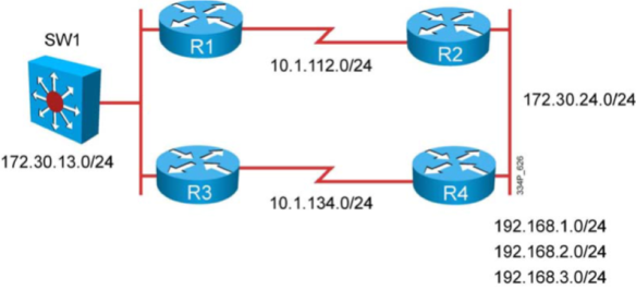
在R1-R4上將所有的界面(LANs ,WANs 及 loopbacks)加入EIGRP 1 的路由協定並檢查其運作
測試由SW上送到 192.168.1.0 及 192.168.2.0的路徑,及是否可到達192.168.1.0 及 192.168.2.0
測試由R1上送到 192.168.3.0 的路徑,及是否可到達192.168.3.0
在R3上更改路徑決定政策,將由來源為 SW上的IP 位址(172.30.13;11)送往192.168.1.0及192.168.2.0時
使用 R1當作下一站位址 (path R3->R1->R2->R4)
驗證R3的決策性路由是否正確運作
在R1上更改路徑決定政策,將R1本身產生的資料流量送往192.168.3.0使用 R3當作下一站位址 (path R1->R3->R4)
STEP1
Rl#
router eigrp 1
network 10.0.0.0
network 172.30.0.0
no auto-sumrnary
R2#
router eigrp 1
network 10.0.0.0
network 172.30.0.0
no auto-summary
R3#
router eigrp 1
network 10.0.0.0
network 172.30.0.0
no auto-summary
R4#
router eigrp 1
network 10.0.0.0
network 172.30.0.0
network 192.168.0.0 0.0.255.255
no auto-summary
STEP2
show ip route & ping
STEP3
在R3上設定 POLICY-BASE ROUTING
Use the following example to configure PBR on router R3 in the lab.
R3#
interface FastEthernetO/O
ip policy route-map RM-PBR
ip access-listextended ACL-PBR
permit ip host 172.30.13.11 192.168.1.0 0.0.0.255
permit ip host 172.30.13.11 192.168.2.0 0.0.0.255
route-map RM-PBR permit 10
match ip address ACL-PBR
set ip next-hop 172.30.13.1
驗證the traffic flow from switch SWl and PBR on R3.
Examine the path of the IP packcts.
timeout is 2 seconds:
sw1#ping 192.168.1.1
Type escape sequence to abort.
Sending 5 , 100-byte ICMP Echos to 192.168.1.1 ,
!!!!!
Success rate is 100 percent (5/5) , round-trip min/avg/max = 58/58/59 ms
timeout is 2 seconds:
R3#debug ip policy
policy routing debugging is on
Note Enable debugging in order to see the policy macth following the ping commands on pod
sw1#ping 192.168.1.1
Type escape sequence to abort.
sending 5 , 100-byte 工CMP Echos to 192.168.1.1 , timeout is 2 seconds:
!!!!!
Success rate is 100 percent (5/5) , round-trip min/avg/max = 51/58/67 ms
R3#
*May 24 14:14:49.025: IP: s=172.30.13.11 (FastEthernetO/O) , d=192.168.1.1 , len
100, FIB policy match
*May 24 14:14:49.025: IP: s=172.30.13.11 (FastEthernetO/O) , d=192.168.1.1 , len
100 , policy match
*May 24 14:14:49.025: IP: route map RM-PBR, item 10 , permit
*May 24 14:14:49.025: IP: s=172.30.13.11 (FastEthernetO/O) , d=192.168.1.1
(FastEthernetO/O) , len 100, policy routed
sw1#ping 192.168.3.1
Type escape sequence to abort.
Sending 5 , 100-byte 工CMP Echos to 192.168.3.1 , timeout is 2 seconds:
!!!!!.
8uccess rate is 100 percent (5/5) , round-trip min/avg/max = 50/57/59 ms
R3#
*May 24 14:15:16.645: IP: s=172.30.13.11 (FastEthernetO/O) , d=192.168.3.1 , len
100 , FIB policy rejected(no match) – normal forwarding
*May 24 14:15:16.645: IP: s=172.30.13.11 (FastEthernetO/O) , d=192.168.3.1
(FastEthernetO/O) , 1en 100 , po1icy rejected – norma1 forwarding
在R1上定義決策性路由影響本身產生流量的傳送路徑
ip local policy route-map RM-LOCAL-PBR
!
ip access-list extended ACL-LOCAL-PBR
permit ip any 192.168.3.0 0.0.0.255
!
route-map RM-LOCAL-PBR permit 10
match ip address ACL-LOCAL-PBR
set ip next-hop 172.30.13.3
. 驗證Verify the traffic flow and PBR on Rl.
R1#ping 192.168.3.1
Type escape sequence to abort.
Sending 5 , 100-byte ICMP Echos to 192.168.3.1 , timeout is 2 seconds:
!!!!!.
Success rate is 100 percent (5/5) , round 咀trip min/avg/max = 56/57/60 ms
R1#traceroute 192.168.3.1
Type escape sequence to abort.
Tracing the route to 192.168.3.1
1 172.30.13.3 0 msec 0 msec 0 msec
2 172.30.13. 工36 msec 32 msec 32 msec
3 10.1.112.2 28 msec 28 msec 28 msec
4 172.30.24.4 28 msec 28 msec *
R1#debug ip po1icy
Po1icy routing debugging is on
Note:Enable debugging in order to see the policy match following the ping commands on pod
router R1
R1#ping 192.168.3.1
Type escape sequence to abort.
Sending 5 , 100-byte ICMP Echos to 192.168.3.1 , timeout is 2 seconds:
!!!!!.
Success rate is 100 percent (5/5) , round-trip min/avg/max = 56/58/60 ms
!
R1#
*May 24 14:28:08.341: IP: s=10.1.112.1 (loca1) , d=192.168.3.1 , 1en 100 , po1icy
match
*May 24 14:28:08.341: IP: route map RM-LOCAL-PBR , item 10 , permit
*May 24 14:28:08.341: IP: s=10.1.112.1 (loca1) , d=192.168.3.1
(FastEthernetO/O) , 1en 100 , po1icy routed
*May 24 14:28:08.341: IP: local to FastEthernetO/O 172.30.13.3
*May 24 14:28:08.401: IP: s=10.1.112.1 (local) , d=192.168.3.1 , len 100 , policy
match
*May 24 14:28:08.401: IP: route map RM-LOCAL-PBR , item 10 , permit
*May 24 14:28:08.401: IP: s=10.1.112.1 (local) , d=192.168.3.1
(FastEthernetO/O) , len 100 , policy routed
*May 24 14:28:08.401: IP: 1ocal to FastEthernetO/O 172.30.13.3
*May 24 14:28:08.457: IP: s=10.1.112.1 (local) , d=192.168.3.1 , len 100 , policy
match
*May 24 14:28:08.457: IP: route map RM-LOCAL-PBR, item 10 , permit
*May 24 14:28:08.457: IP: s=10.1.112.1 (local) , d=192.168.3.1
(FastEthernetO/O) , len 100 , policy routed
*May 24 14:28:08.457: IP: local to FastEthernetO/O 172.30.13.3
*May 24 14:28:08.517: IP: s=10.1.112.1 (local) , d=192.168.3.1 ,len 100, policy
Match
R1#ping 192.168.1.1
Type escape sequence to abort.
Sending 5 , 100-byte ICMP Echos to 192.168.1.1, timeout is 2 seconds:
! ! ! ! !
Success rate is 100 percent (5/5) ,言。und-trip min/avg/max = 56/56/60 ms
R1#
*May 24 14:28:18.977: IP: s=10.1.112.1
rejected — normal forwarding
*May 24 14:28:19.033: 工P: s=10 .1. 112.1
———————————————————————————————————
LAB 6-1 & 6-2 BGP
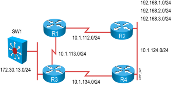
TASK1
- 在 R1-R4 上 設定及啟用 BGP 協定
- R3 加入 BGP AS 130 ,R1 加入 BGP AS 100 ,並且在 R3 & R1 之間建立 EBGP 的 PEER 關係
- R3 加入 BGP AS 130 ,R4 加入 BGP AS 400 ,並且在 R3 & R4 之間建立 EBGP 的 PEER 關係
- R2加入 BGP AS 200 並和,在AS 100 的R1 加入 之間建立 EBGP 的 PEER 關係
- 在 AS200 的R2 和 加入 BGP AS 400的 R4 之間 建立 EBGP 的 PEER 關係
- 在 AS 130 ,100,400之間的peer 需使用 MD5 進行驗證以達到最安全的交換訊息方式
-
驗證所有 PEER 正確建立鄰居,及接收BGP路由更新訊息
SOL:
STEP 1: 在 R1-R4 使用 show ip int brief | section up 找出所有使用中的界面及IP位址
STEP 2 : 設定基本 BGP PEER關係
R1#
router bgp 100
no synchronization
bgp log-neighbor-changes
ne 工ghbor 10.1.112.2 remote-as 200
neighbor 10.1.113.3 remote-as 130
neighbor 10.1.113.3 password cisco
no auto-summary
R2#
router bgp 200
no synchronization
bgp log-neighbor-changes
neighbor 10.1.112.1 remote-as 100
neighbor 10.1.124.4 remote-as 400
no auto-summary
R3#
router bgp 130
no synchronization
bgp log-neighbor-changes
neighbor 10.1.113.1 remote-as 100
neighbor 10.1.113.1 password cisco
neighbor 10.1.134.4 remote-as 400
neighbor 10.1.134.4 password cisco
no auto-summary
R4#
router bgp 400
no synchronization
bgp log-neighbor-changes
neighbor 10.1.124.2 remote-as 200
neighbor 10.1.134.3 remote-as 130
neigrilior 10.1.134.3 password cisco
no auto-summary
STEP3:驗證
在 R1-R4 上 使用
Rx# Show ip bgp summary
Rx# Show ip bgp neighbor
的指令檢查是否鄰居正確建立
TASK2
- R3利用 NETWORK 指令 宣告直連的網路 172.30.13.0/24 給之前建立的EBGP 鄰居
- R3 利用 REDISTRIBUT 的方式宣告 本身的 loop Back界面給 10.3.3.3/32 給PEER AS 100, 及 400
- 設定 R2 宣告 192.168.x.0的 網路 給鄰居的 AS, 除了宣告各別的192.168.x.0 /24 之外只要有任合
一筆 192.168.x.0/24存在就只送出 192.168.0.0/16 的聚合網路
- 檢查 R1,R2,R4 是否有 172.30.13.0/24 , 10.3.3.3/32 的路由存在 ,且 R1,R3,R4 上是否有192.168.0.0/16 的路由存在(Routing Table & BGP TABEL)
Step 4 宣告BGP的網路
R3# router bgp 130
network 172.30.13.0 mask 255.255.255.0
redistribute connected route-map RM-BGP
!
ip access-l工ststandard ACL-BGP permit 10.3.3.3
!
route-map RM-BGP permit 10 match ip address ACL-BGP
R2#
router bgp 200
network 192.168.1.0
network 192.168.2.0
network 192.168.3.0
aggregate-address 192.168.0.0 255.255.0.0 summary-only
STEP 5 路由表及 BGP table驗證
在 R1,R2,R4 使用 Rx# Show ip bgp 及 sh ip route 的指令進行驗證 172.30.13.0/24 及 10.3.3.3/32 存在與否
在 R1,R3,R4 使用 Rx#show ip bgp 及 s hip route 的指令進行驗證 192.168.0.0/16是否存在
LAB 6-2 BGP

各設備加入的 AS號碼
AS130 和 AS 100 建立 BGP PEER (R3-R1)
AS200 和 AS 100 建立 BGP PEER(R2-R1)
AS400 和 AS 200 建立 BGP PEER(R4-R2)
R3宣告172.30.13.0 /24資訊給 PEER 的 AS
R2宣告192.168.1.0 /24,192.168.2.0/24 ,192.168.3.0/24 資訊給 PEER 的 AS
更改BGP的預設選擇路徑的方式,封包由AS103送往AS200時將使用經由 10.1.131.1的路徑將被當成主要路徑,
10.1.113.1的路徑為次要路徑
建立額外的BGP PEER
SW1加入AS130 和在AS 100的R1建立 E-BGP SESSION
在AS130 的R3 和在AS 400的 R4建立 E-BGP SESSION
在AS130 的 R3和 SW 建立 i-BGP SESSION
移除AS130 R3 和 AS100 R1之間的 E-BGP PEER
檢查 EBGP 的 PEER 關係 ,及路由表中存在需要的路由 ,以及AS130的主要傳送及接收路徑
影響來自AS200 進入 AS130的路徑將偏好使用R1
SOL:
STEP1:建立基本BGP peer
R1#
router bgp 100
no synchronization
bgp log-neighbor-changes
neighbor 10.1.112.2 remoteas200
! TO R2
neighbor 10.1.113.3 remote-as 130
! TO R3
neighbor 10.1.131.3 remote-as 130
! TO R3
no auto-summary
R2#
router bgp 200
no synchronization
bgp log neighbor-changes
neighbor 10.1.112.1 remote-as 100
! TO R1
neighbor 10.1.124.4 remote-as 400
! To R4
no auto-summary
R3#
router bgp 130
no synchronization
bgp log-neighbor-changes
neighbor 10.1.113.1remote-as 100
! To R1
neighbor 10.1.131.1 remote-as 100
! To R1
no auto-summary
R4#
router bgp 400
no synchronization
bgp log-neighbor-changes
neighbor 10.1.124.2 remote-as 200
! TO R2
no auto-summary
STEP2:
RX# show ip bgp summary
RX# show ip bgp
STEP 3 宣告網路
R2#
router bgp 200
network 192.168.1.0
network 192.168.2.0
network 192.168.3.0
R3#
router bgp 130
network 172.30.13.0 mask 255.255.255.0
STEP4
RX# show ip bgp
RX# show ip route
STEP 5修正路徑
R3#
router bgp 130
neighbor 10.1.113.1 route-map RM-MED out
!影響返回的路徑,用10.1.131,1當作較佳路徑
neighbor 10.1.131.1 route-map RM-WEIGHT in
!影響傳送路徑使用10.1.131.1當作主要傳送路徑
route-map RM-WEIGHT permit 10
set weight 1000 route-map RM-MED permit 10
route-map RM-MED permit 10
set metric 1000
天線(通信中的重要部件)的基礎知識
|
|||||||
|
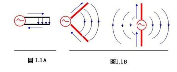
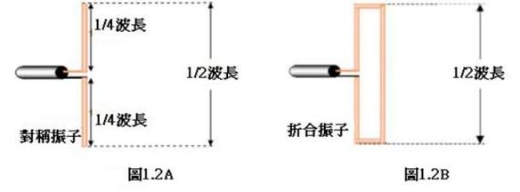


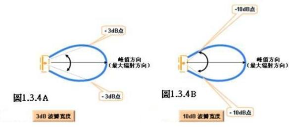
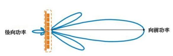
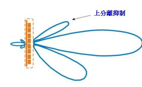


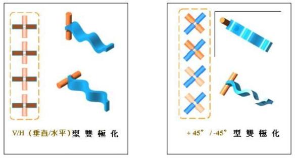
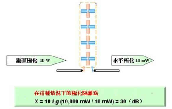
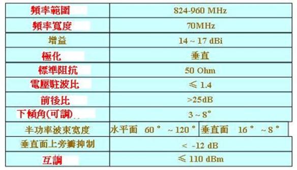
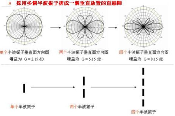
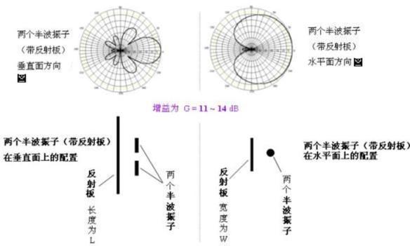
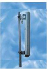


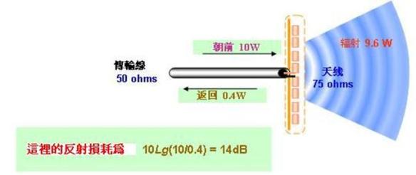
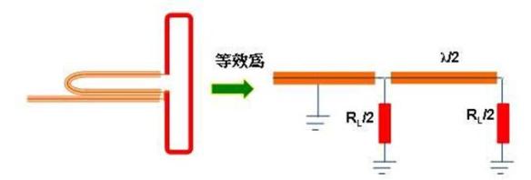
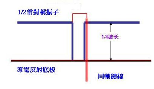
WLAN之ISM與UNII頻帶釋疑(擷錄部分)
WLAN之ISM與UNII頻帶釋疑(擷錄部分)
ISM 頻帶的特色是「牛驥同皁」,也就是所有的設備都可使用(共有制);而UNII頻帶帶給WLAN族群的好處是純粹作通訊使用,故不會有微波爐等干擾情況出現。
Hedy Lamarr在二次大戰期間提出跳頻展頻(FHSS)的構想並申請專利,她自德國逃到美國而成為好萊塢紅星,可惜FHSS被軍方秘密採用,也沒付給Hedy任何權利金!
FHSS之後有了DSSS(直序展頻),後來又有了OFDM技術。這三種技術在軍中被廣泛採用,直到民間業者不斷爭取無需執照的商業運用,聯邦通訊委員會(FCC)才在1986年開放902~928MHz(簡稱900MHz頻段),2.400~2.4835GHz(簡稱2.4GHz頻段),以及5.725~5.875(簡稱5.8GHz頻段)等三段頻帶,稱為ISM(Industrial、Scientific與Medical)頻帶。
市面上出現許多的ISM設備,如Walkie Talkie、嬰兒監視器、無線話機、塑膠袋封口機、微波爐等,而由於902~928MHz可用的國家並不多,廠商多已朝2.4GHz開發這些設備,目前這設備更開始朝向5GHz發展,例如不少微波爐業者在開發5GHz磁控管,若成本允許,則5.8GHz微波爐很快將上市。
ISM Band的特色是「牛驥同皁」,也就是所有的設備都可使用,因此其使用效率遠高於其他頻段。論起此頻帶對國家的實用性,國防用途或行動通訊都得靠邊站,筆者預測美國的MMDS頻道(2.1、2.5與2.7GHz)應遲早會落到WLAN的地盤,雖然3G行動通訊業不停在遊說FCC希望取得這三個頻道,而且看來2.1GHz落袋已沒問題。
1996年各國政府都在推動國家資訊基礎建設(National Information Infrastructure;NII)計劃而增加不少光纖通訊設施,美國政府為弭平數位落差,而再開放了無需執照的UNII(Unlicensed NII)頻帶,期望新的通訊業者能藉由這個頻段,以低廉的價格提供消費者寬頻服務,使得全民都能有機會上網而不會造成Internet弱勢族群。
UNII頻帶帶給WLAN族群的好處是純粹作通訊使用,故不會有微波爐等干擾情況出現。但是UNII頻帶在5GHz中共有三段,分別是UNII-1的5.125~5.25GHz、UNII-2的5.25~5.35GHz,以及UNII-3的5.725~5.825GHz三段;而UNII-3竟然與ISM頻段中的5.8GHz重疊,故讓許多人產生了疑惑。
FCC功率規定與計算
UNII-3設備只能用於室外,其輸出功率規定與ISM相同;亦即若使用全向天線,則輸入天線的功率(Intentional Radiator;IR)為1W、天線的輸出功率(Effective IR Power;EIRP)為4W。假設一個6dBi的全向天線,若輸入功率是1W,亦即30dBm,則天線的輸出功率就是36dBm,亦即4W。
要了解IR及EIRP的計算,必須知道dB、dBm、dBw、dBi等觀念。
dB就是分貝(Decibel),假設有一個放大器能將輸入的功率放大10倍,若套到10×Log(x)公式,則為10×Log(10)=10×1=10,亦即提昇10個dB,我們說該放大器的增益為10dB。因為100.3=2,故10Log(2)=3,所以3dB表示2倍。
同理,4dB表示2.5倍、5dB表示3倍、6dB為4倍、13dB為20倍、60dB為100萬倍、90dB表示10億倍。
我們再定義一個1/1000W為一個dBm,m表示 Milliwatt。因為10×log(1)=0,故0dBm表示1mW,而10dBm為0dBm的10倍,亦即10mW,13dBm為20mW;若dB數為負值,則為縮小的倍數,如-90dBm為10的-12W,亦即0.000000000001W。dBw的w表示1W,故1dBw=30dBm、20dBw=50dBm、0dBw表示30dBm。
dBi的i表示Isotropic Antenna,這是一個理想天線,它能以球狀方式向外發送能量,而且天線本身不會產生損耗。這種天線實際上作不出來,太陽可算一個實例。但數學模型很容易建立,故任何天線都可與Isotropic天線比較且定義其增益值。故理想天線本身的增益值一定是0dBi,且它的立體放射圖形一定是球型。
若找到一支0dBi的天線,是否表示它是理想天線?需檢查其特性曲線圖形是否為球型,通常是全向或半方向天線。全向天線在水平方向為360度,但垂直方向有限,好比一個甜甜圈。故若某全向天線為0dBi,表示其水平方向(增益最大方向)等於Isotropic天線的能量,而其它方向的增益比Isotropic天線小,表示被天線本身衰減掉了;此時我們不必討論Isotropic天線的輸入功率,因為輸入功率等於完全被以球面平均放射而出。
考慮3dBi的全向天線,表示其水平方向之增益等於Isotropic天線的2倍,若本身無衰減,則垂直方向的角度為上下各45度,這相當於無損耗的理想天線,不可能做得出,故實際產品約在上下30度。
考慮一個16dBi的全向天線,為理想天線的40倍強,扣掉衰減,180度除以60為3度。想像機房若使用上下角度只有3度的天線,它只能對四周幾乎相同高度的大樓做傳輸,故全向天線不可能有人做超過16dBi的天線。
若水平角度也能壓縮,例如20dBi的盤式天線,假設水平與垂直角度各縮小10倍,亦即水平36度與垂直18度,取平均則各為27度,在扣掉衰減因素,則放射角度各為20度以內。衛星盤式天線的角度通常在2度以內。角度兩度的天線很貴,且安裝時需對得很準,大風都可能會影響其方向。WLAN所用的高方向天線通常不會超過30dBi。
假設你有一張SMC的2532W-B 23dBm,亦即200mW的PCMCIA WLAN網卡,而將其直接接上30dBi的天線,亦即IR是23dBm,則EIRP輸出是200W,亦即53dBm。家用微波爐內也只有750W,若你在30dBi天線前站5分鐘,身體某處會開始冒煙,肉會變黑!
前述的超高功率網卡是駭客最愛,因為他可以躲得很遠而以高方向天線進行偷聽或干擾動作。一般WLAN網卡只有13dBm,亦即20mW。
FCC對於ISM Band的功率規定,是依據天線而分為兩大類,若是全向天線則屬於PtMP(Point-to-MultiPoint)類,若為方向性天線則為PtP(Point-to-Point)類。PtMP的規定很好記,EIRP的最大值為4W,亦即36dBm,例如IR功率為30dBm,則天線最大增益為6dBi。
PtP則需死背一個起始值,也就是前例。當IR為30dBm,方向性天線的增益為6Bi,則EIRP為最大值36dBm。當天線的增益越高時,EIRP可適當提昇。FCC規定若dBi自6dBi每增加3個dBi,IR只需相對降低1個dB,故若搭配30dBi的高方向天線,IR需降低8dB。所以22dB的IR配合30dBi的天線,則輸出為52dBw。所以前述的SMC卡片搭配30dBi天線使用,已超過了FCC許可範圍,不過52dBm也約160瓦,同樣非常危險。故這些高功率天線的使用,務必聘請RF職業安裝人員來完成。
對2.4GHz與5.8GHz的ISM頻道功率規定有所了解,尤其是搭配外接天線時,心中需隨時有這些功率觀念,才會產生危險意識。
UNII頻帶
當UNII三段頻帶被推出時,WLAN業者自是鼓掌歡迎,因為他們的主要市場是在室內運用。但做室外橋接器的廠商則很不是滋味,因為UNII-3頻帶竟然含在5.8GHz之中,表示室外通訊設備還是得「牛驥同皁」,而無法得到清靜的傳輸頻道。
UNII-1為5.15~5.25GHz,只能做為通訊使用,不見得只有802.11a設備能存在,Bluetooth 2.0及HiperLAN 2都可用這一段頻帶。它的天線必須與設備一體成型,即使用者不能自行更換較高增益天線。若天線為4dBi,則最大IR為50mW,即EIRP為200mW,只能用於室內,而且Bluetooth 2.0與HiperLAN2看來產品不會出現,故UNII-1的802.11a設備目前能享受清爽而無干擾之頻道。
UNII-2為5.25~5.35GHz,亦只能做為通訊使用,其天線不見得必須與設備一體成型。若天線為4dBi,則最大IR為250mW,亦即EIRP為1W,可用於室內或室外;UNII-2的802.11a設備目前亦能享受清爽而無干擾的頻道。
因為只有這兩個頻帶可用於室內,主攻室內設備的WLAN廠商只對這兩個頻道有興趣,而且有不少廠商的設備同時支援UNII-1與UNII-2頻帶。FCC規定這些設備必須符合UNII-1的規定,只能用於室內,EIRP最大傳輸功率為200mW,且天線必須與主機連為一體。
UNII-3為2.725~2.825GHz,與5.8GHz的ISM頻道的前段有80%重疊。因為屬於ISM之一段,其功率規定與ISM幾乎一樣,但調變方式還是略有不同。UNII-3對於調變方式幾乎沒有任何限制,但ISM則原來只有FHSS與DSSS兩種,於2001年5月才在2.4GHz對WiLAN的OFDM設備開放特許,故造成802.11g大轉彎,而放棄PBCC改朝OFDM發展。
UNII-3設備若使用全向天線,最大功率規定為EIRP 4W,若搭配方向性天線,則幾乎沒有限制。
做2.4GHz與5.8GHz橋接器的廠商,一直在向FCC哭訴,想要一塊只有通訊設備存在的乾淨頻帶,這個願望不太容易實現。
新的UNII-2頻段
FCC於今(2003)年5月15日公佈NPRM(Notice of Proposed Rule Making)將開放5.470~5.725GHz頻段作為UNII-2使用,將使得UNII總頻寬由300MHz增加80%而達525MHz,這對傳統WLAN廠商又是一個大利。此NPRM由6月4日開始算120天內若無反對意見,將交由國會立法而生效。
由於此NPRM頻道有歐洲血統,故歐洲規定的DFS(Dynamic Frequency Selection)及TPC(Transmit Power Control)功能,也將包括於UNII規定之中;亦即不只這段新頻道,將來原有的UNII也需支援DFS及TPC功能。DFS能讓設備避開正被使用的頻道,TPC能依據彼此距離而自動降低彼此的傳送功率,這兩個是非常重要的節約頻道使用功能,筆者覺得2.4GHz不久亦將採用這個功能。
NPRM又再度打擊了橋接器廠商,因為其目的是增加UNII-2,而非UNII-3的頻帶。雖然UNII-2也可用於室外,但功率僅為UNII-3的四分之一,故室外橋接器的廠商均專注於5.8GHz系統的製造。雖然橋接器廠商不斷遊說FCC,但FCC認為以數量上而言,802.11a WLAN設備還是遠勝於室外橋接器的市場,故將NPRM的新頻道作為UNII-2使用,等於是採中庸之道,讓WLAN或橋接器廠商兩者都可使用。
橋接器廠商感覺不平的是,NPRM提出的頻道是為了與歐洲ETSI所開放之頻帶吻合,但ETSI在此頻帶的可用功率與UNII-3吻合,為何美國要將頻率降低而成為UNII-2?
目前已有橋接器廠商推出「雙環」橋接器產品,以UNII-2照顧半徑5公里以內的客戶,而以5.8GHz照顧半徑5公里外而達20公里的客戶,這是很有創意的雙頻設備。目前各UNII頻帶均有4個頻道,故室內或室外各有8個頻道可用,未來若NPRM將UNII-2增加10個頻道而達14個頻道,則UNII能提供室內或室外各18個頻道可用,而2.4GHz ISM卻只有3個頻道可用。
2003年6月ITU在日內瓦的WRC-03 (World Radio Conference)會議,各國承諾對UNII開放一致的頻段,所以FCC才會有NPRM的提出,以與ETSI一致,預計台灣很快會跟進美國的動作,故UNII在全球的通行比率會超過2.4GHz。在台灣只有UNII-2及UNII-3可用,UNII-1可能是軍方有特殊用途。在美國UNII-1只能用於室內且功率最小,顯然在室外有很重要的用途存在,例如巡弋飛彈的導航。大陸是全球唯一規定2.4GHz只能用在室內的國家,而5GHz需要使用執照的頻帶,只能用在室外。
FCC的調變規定
關於調變技術的規定,FCC原先有很嚴格的規定,現在則越來越寬鬆。例如802.11標準推出之時,FHSS系統在30秒內必須多次掃描完畢整個75個頻道,平均在每個頻道停留的時間(Dwell Time)不得超過0.4秒。例如一傳送者每個頻道使用100ms作為Dwell Time,則需7.5秒再多一點,可以掃描完75個頻道(每個頻道100mS)而回到最初頻道。會多一點時間的原因是額外的Hop Time。重複4次會使得每個頻道使用了400mS,而總時間剛好超過30秒一點點(>7.5秒×4),此點符合FCC的規定;另一例子,是FHSS的Dwell Time為200mS,則能在30秒內掃描2次。
由於2000年8月31日FCC採用WBFH(Wide Band Frequency Hopping)的NPRM,而改變了FHSS之相關規定,造成「8/31/2000之前」及「8/31/2000之後」的2種規定,且FCC讓廠商選擇使用何者,因此廠商若推出FHSS系統,可選擇其中任何一種規定。若選擇其中一種規定,則設備必須完全符合該規定。
在2000年8月31日修訂為一組跳躍只需跳躍15次,但也有它的需求。例如若每個頻道為5MHz寬,則最大功率為125mW。因為若頻道越寬,則傳送所需功率可以越低,這是展頻系統的基本特性。簡單地說,FCC要求跳躍次數乘以頻道寬度必須為75。例如若跳躍為25次,則頻寬為3MHz;若跳躍為15次,則頻寬為5MHz;若跳躍為20次,則頻寬為3.75MHz。
注意只能選擇「8/31/2000之前」及「8/31/2000之後」,而且不能混合這兩種規定。HomeRF 2.0為唯一採用WBFH的系統,可惜由於不敵WLAN,而於今年2月宣佈解散。
關於DSSS的限制,FCC有Processing Gain的需求。DSSS技術為了克服Multipath等現象所造成的信號損壞,而將資料信號以較高速度的Bit順序作傳送,稱為Chipping Code或Processing Gain。好比我們要將「1」送出,但實際上我們送出了10個「Chip」,表示Processing Gain為10。很高的Processing Gain能增加信號抵抗干擾的能力。FCC規定的Processing Gain至少需為10,而大部分的產品都採用小於20之值。IEEE 802.11的DSSS則將Processing Gain定為11。
例如802.11使用的Barker Code以11個Chip的「00110011011」表示1,另以「11001100100」表示0,假如接收到的信號是「00110010111」,則與「1」比有2個錯誤,而與「0」比則有9個錯誤,所以收到的信號一定是「1」。所收到的信號雖有部分錯誤,但不影響資料的傳輸。
若使用的Chip越多,即表示Processing Gain越高,也就是克服不良環境的能力越強。這些Chip是依照順序在22MHz寬的Channel中送出,故任一瞬間此22MHz的信號均相同,也因為這頻道很寬,所以展頻系統能克服窄頻干擾。
在2001年5月10日,FCC開放2.4GHz之OFDM產品的同時,另外對DSSS與FHSS的規定也更為放寬。關於DSSS,FCC取消了Processing Gain的限制;對於FHSS,FCC允許一次以1MHz跳躍15次即可,即它可Bypass許多頻道而不做跳躍,原來的規定是每次必須跳完整個75MHz才能重新開始。此舊規定讓藍芽會嚴重干擾DSSS系統的運作,故許多運用802.11b技術的場合,貼有「禁用藍芽」標誌。有了此規定,希望未來的藍芽系統,能聰明地跳過802.11b或802.11g系統所正在使用的頻帶。
FCC對於WLAN還有許多使命待完成。WLAN 橋接器廠商真正想要的是開放低於4GHz之頻帶,因為頻率越低,則NLOS(Non-Line-of Sight)的性能越強,即RF信號可用其天生較佳的反射、繞射與不易被牆壁吸收等特性,可以像手機信號一般地無所不在;且能讓傳送者與接收者之間沒有直接路徑,彼此還是能夠互通。
OSPF LSA Details
OSPF LSA Details
Several types of LSAs exist. This section discusses the nine types of LSAs documented in Table 8-2.
| Table 8-2. Types of LSA | ||
| Type | LSA | Functionality |
| 1 | Router | Defines the state and cost of the link to the neighbor and IP prefix associated with the point-to-point link. |
| 2 | Network | Defines the number of routers attached to the segment. It gives information about the subnet mask on that segment. |
| 3 | Summary network | Describes the destination outside an area but within the OSPF domain. The summary for one area is flooded into other areas, and vice versa. |
| 4 | Summary ASBR | Describes the information about the ASBR. In a single area, there will be no summary Type 4 LSA. |
| 5 | External | Defines routes to destination external to OSPF domain. Every subnet is represented by a single external LSA. |
| 6[*] |
Group membership | |
| 7 | NSSA | Defines routes to an external destination, but in a separate LSA format known as Type 7. |
| 8[*] |
Unused | |
| 9–11[*] |
Opaque | |
[*] Type 6 is used for group membership in Multicast OSPF (MOSPF), which is not implemented by Cisco. Type 8 is unused, and Types 9–11 are used for Opaque LSA, which is not used for route calculation but is used for MPLS traffic engineering, which is beyond of the scope of this chapter. More information about Opaque LSA can be found in RFC 2370.
Each LSA has a 20-byte common LSA header, the format for which is illustrated in Figure 8-7.
Figure 8-7. Common LSA Header Format
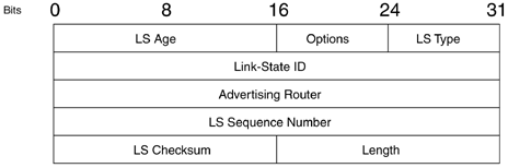
The list that follows describes the fields in the LSA header:
- LS Age— Gives the time, in seconds, since the LSA originated. The maximum age of the LSA is 3600 seconds; the refresh time is 1800 seconds. If the LS age reaches 3600 seconds, the LSA must be removed from the database.
- Options— Discussed earlier in the section “Hello Packets."
- LS Type— Represents the types of LSA, several of which are documented in Table 8-2.
- Link-State ID— Identifies the portion of the network that is being described by the LSA. This field changes according to the LS type.
- Advertising Router— Represents the router ID of the router originating the LSA.
- LS Sequence Number— Detects old or duplicate LSAs. Each successive instance is given a successive sequence number. The maximum sequence number is represented by 0x7FFFFFFF. The first sequence number is always 0x80000001. The sequence number 0x80000000 is reserved.
- LS Checksum— Performs checksum on the LSA, not including LS age. An LSA can be corrupted during flooding or while kept in the memory, so this checksum is necessary. This field cannot have a value of 0 because 0 means that the checksum has not been performed. The checksum is performed at the time of LSA generation or when the LSA is received. It is also performed every CheckAge interval, which, by default, is 10 minutes.
- Length— Includes the length of the LSA, including the 20-byte header.
Router LSAs are generated by each router for each area to which the router belongs. These packets describe the states of the router’s link to the area and are flooded only within a particular area. All the router’s links in an area must be described in a single LSA.
The router LSA floods throughout the particular area; however, the flooding of this LSA is limited within an area. The router LSA of a router cannot exist outside the area; otherwise, every single router in OSPF would have to carry huge amounts of detailed information. Those details remain within an area. The router indicates whether it’s an ABR, ASBR, or an endpoint of a virtual link.
Figure 8-8 shows the packet format for the router LSA.
Figure 8-8. Router LSA Packet Format
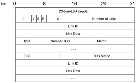
The list that follows describes the fields within the router LSA packet:
- Bit V— This bit is used to determine whether it’s an endpoint of a virtual link.
- Bit E— This bit is used to determine whether this router is an Autonomous System Boundary Router (ASBR).
- Bit B— This bit is used to determine whether this router is an Area Border Router (ABR).
- Number of Links— This includes the number of router links. Note that the router LSA includes all the router links in a single LSA for an area.
- Link ID, Link Data, and Type— The Type field represents the four types of router links. The other two fields, Link ID and Link Data, represent the 4-byte IP address value, depending on the network type. One thing to note here is that there can be two types of point-to-point links, numbered and unnumbered. In case of numbered point-to-point links, the Link Data field contains the interface address that connects to the neighbor. In the case of unnumbered links, the Link Data field contains the MIBII Ifindex value, a unique value that is associated with every interface. It normally has values starting from 0, as in 0.0.0.17. Table 8-3 lists all possible values for the Link ID and Link Data fields.
- ToS and ToS Metric— These fields represents the type of service and are normally set to 0.
- Metric— This field contains the OSPF cost of a specific link. The formula to calculate OSPF cost is 108/Link bandwidth. For example, the metric of a Fast Ethernet interface would be 1. Metric is determined directly from the interface bandwidth, which is configurable. This formula for metric calculation can be overridden by two methods. The first method uses the ip ospf cost
cost command under the interface. The second method uses the auto-cost reference-bandwidth
reference-bandwidth command under router ospf configuration. The reference bandwidth actually changes the 108 value in metric calculation formula.
Example 8-1 shows the output of a router LSA from a Cisco router.
RouterB#show ip ospf database router 141.108.1.21
LS age: 1362
Options: (No TOS-capability, DC)
LS Type: Router Links
Link State ID: 141.108.1.21
Advertising Router: 141.108.1.21
LS Seq Number: 80000085
Checksum: 0xE914
Length: 60
Area Border Router
Number of Links: 3
Link connected to: another Router (point-to-point)
(Link ID) Neighboring Router ID: 141.108.1.3
(Link Data) Router Interface address: 141.108.1.2
Number of TOS metrics: 0
TOS 0 Metrics: 64
Link connected to: another Router (point-to-point)
(Link ID) Neighboring Router ID: 141.108.3.1
(Link Data) Router Interface address: 141.108.1.2
Number of TOS metrics: 0
TOS 0 Metrics: 64
Link connected to: a Stub Network
(Link ID) Network/subnet number: 141.108.1.2
(Link Data) Network Mask: 255.255.255.255
Number of TOS metrics: 0
TOS 0 Metrics: 0
The output in Example 8-1 shows three links. A few important things to note in this output (as highlighted) are as follows:
- In normal situations, the LS Age field should be less than 1800.
- In the case of a router LSA, the Link-State ID field and advertising router should have the same value as they do in Example 8-1.
- This router is an ABR and has three router links.
With every point-to-point link, there is a stub link to provide the subnet mask of the link. In this example, two point-to-point links and one stub link are associated with these two point-to-point links because the network type is point-to-multipoint. So, if there are 300 point-to-point links, the router will generate 300 point-to-point links as well as 300 stub links to address the subnet associated with each point-to-point link. The point-to-multipoint network type is a better choice in this case, for two reasons:
- Only one subnet is required per point-to-multipoint network.
- The size of the router LSA is cut in half because there will be only one stub link to address the subnet on a point-to-multipoint network. This link is usually a host address.
If you drew a network topology out of this information, you would actually see a small part of OSPF network, as shown in Figure 8-9.
Figure 8-9. Network Topology Drawn from the Information Contained in the Router LSA
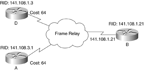
The DR generates the network LSA. If no DR exist (for example, in point-to-point or point-to-multipoint networks), there will be no network LSA. The network LSA describes all the routers attached to the network. This LSA is flooded in the area that contains the network, just like the router LSA. Figure 8-10 shows the packet format for the network LSA.
Figure 8-10. Network LSA Packet Format
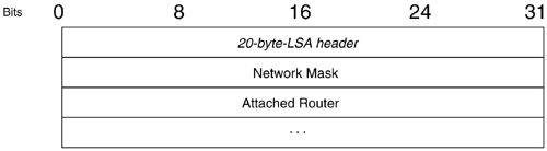
The network LSA has two important components:
- Network Mask— This field indicates the network mask associated with the transit link.
- Attached Router— This field includes the router ID of each router associated with this transit link. The designated router also lists itself in attached routers.
Example 8-2 shows the output of a network LSA from a Cisco router.
Example 8-2 Network LSA Output
RouterA#show ip ospf database network 141.108.1.1
Routing Bit Set on this LSA
LS age: 1169
Options: (No TOS-capability, DC)
LS Type: Network Links
Link State ID: 141.108.1.1 (address of Designated Router)
Advertising Router: 141.108.3.1
LS Seq Number: 80000002
Checksum: 0xC76E
Length: 36
Network Mask: /29
Attached Router: 141.108.3.1
Attached Router: 141.108.1.21
Attached Router: 141.108.1.3
The last three lines of output in Example 8-2 show that three routers are attached to this transit link. Also, the network mask on this transit link is /29. There are two important things to remember here:
- The Link-State ID field always contains the IP address of the DR.
- The advertising router field always contains the router ID of the DR.
You can similarly draw a network topology from the information contained in the network LSA showing the number of attached routers and the network mask on the link.
Figure 8-11 shows the network topology drawn from the information in the network LSA.
Figure 8-11. Network Topology Drawn from the Information Contained in the Router LSA
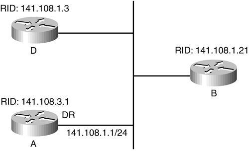
The summary LSA describes the destination outside the area, but still within the AS. Summary LSAs are generated when there is more than one area provided and Area 0 is configured. The purpose of the summary LSA is to send the reduced topological information outside the area. Without an area hierarchy, it will be difficult to scale the huge topological information in a single area. This LSA does not carry any topological information; it carries only an IP prefix. This LSA is originated by the ABR, as follows:
-
From a nonbackbone to a backbone area, summary LSAs are generated for:
– Connected routes
– Intra-area routes
Only intra-area routes are advertised into the backbone to avoid loops. If there are any inter-area routes coming from nonbackbone area it means that the backbone is discontiguous. A discontiguous backbone is not allowed in OSPF networks.
-
From a backbone to a nonbackbone area, summary LSAs are generated for the following:
– Connected routes
– Intra-area routes
– Interarea routes
Two types of summary LSAs exist:
- Type 3— Used for the information about the network
- Type 4— Used for the information about the ASBR
Figure 8-12 shows the packet format for the summary LSA.
Figure 8-12. Summary LSA Packet Format
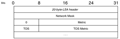
The list that follows describes the fields within the summary LSA packet:
- Network Mask— For the Type 3 summary LSA, this field contains the network mask associated with the network. For the Type 4 summary LSA, this field must be 0.
- Metric— This field represents the cost of the network.
- ToS and ToS Metric— These fields are normally set to 0.
Both the Type 3 and Type 4 summary LSAs use the same packet format. The important things to remember about summary LSA Types 3 and 4 are as follows:
- The network mask in Type 3 contains the subnet mask value of the network.
- The network mask field must be 0.0.0.0 in Type 4 LSAs.
- In Type 3 LSAs, the Link-State ID field should have the network number.
- In Type 4 LSAs, the Link-State ID field should have the router ID of the ASBR.
- The advertising router field must contain the router ID of the ABR generating the summary LSA. This is true for both Type 3 and 4 LSAs.
There is one special case of summary LSAs—in cases when a stub-area ABR generates a summary default route. In this case, the Link-State ID field as well as the network mask must be 0.0.0.0.
Example 8-3 shows the output of a summary LSA from a Cisco router.
Example 8-3 Summary Network LSA Output
RouterB#show ip ospf database summary 9.9.9.0
LS age: 1261
Options: (No TOS-capability, DC)
LS Type: Summary Links(Network)
Link State ID: 9.9.9.0 (summary Network Number)
Advertising Router: 141.108.1.21
LS Seq Number: 80000001
Checksum: 0xC542
Length: 28
Network Mask: /24
TOS: 0 Metric: 10
The Link-State ID field here is the network 9.9.9.0, and the network mask is /24. The Link-State ID field in summary LSAs Type 3 will always contain the network number that the summary LSA is generated for, along with the network mask. The summary LSA here is generated for 9.9.9.0/24, as shown in Figure 8-13.
Figure 8-13. Network Diagram Where ABR Router Generates the Summary LSA
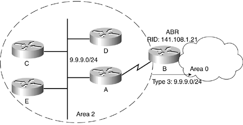
Example 8-4 shows summary ASBR LSA output.
Example 8-4 Summary ASBR LSA Output
RouterB#show ip ospf database asbr-summary 141.108.1.21
LS age: 1183
Options: (No TOS-capability, No DC)
LS Type: Summary Links(AS Boundary Router)
Link State ID: 141.108.1.21 (AS Boundary Router address)
Advertising Router: 141.108.1.1
LS Seq Number: 80000001
Checksum: 0x57E4
Length: 28
Network Mask: /0
TOS: 0 Metric: 14
The output from Example 8-4 shows that this is summary LSA Type 4. The network mask is 0, and the Link-State ID is the router ID of the ASBR. In case of Type 4, the Link-State ID is always the router ID of the ASBR. The Network Mask field must always be 0 because this is the information about a router (ASBR), not a network. Figure 8-14 shows the net-work diagram based on the output shown in Example 8-4.
Figure 8-14. Network Diagram Where ABRs Generates the Type 4 Summary LSA
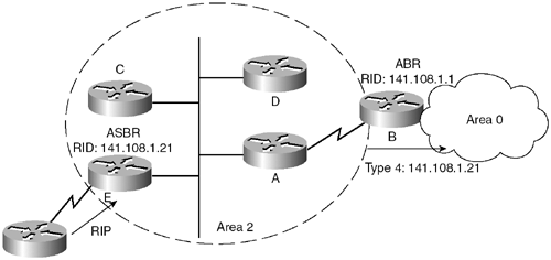
Example 8-5 shows the default summary ASBR LSA output.
Example 8-5 Default Summary LSA Output
RouterB#show ip ospf database summary 0.0.0.0
LS age: 6
Options: (No TOS-capability, DC)
LS Type: Summary Links(Network)
Link State ID: 0.0.0.0 (summary Network Number)
Advertising Router: 141.108.1.21
LS Seq Number: 80000001
Checksum: 0xCE5F
Length: 28
Network Mask: /0
TOS: 0 Metric: 1
The output in Example 8-5 shows that the Link-State ID and network mask are 0.0.0.0. Because this is the information about a default route, it must have 0.0.0.0 in the Link-State ID, and the network mask must be 0.0.0.0. These two pieces of information then represent the default route as 0.0.0.0/0. This summary default will be present in a stubby area situation, as shown in Figure 8-15.
Figure 8-15. Network Diagram Where ABR Generates a Summary Default LSA
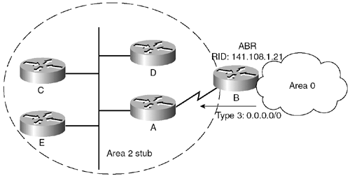
The external LSA defines routes to destinations external to the autonomous system. Domain-wide, the default route can also be injected as an external route. External LSAs are flooded throughout the OSPF domain, except to stubby areas. To install an external LSA in the routing table, two essential things must take place:
- The calculating router must see the ASBR through the intra-area or interarea route. This means that it should have either a router LSA for the ASBR or a Type 4 LSA for the ASBR, in case of multiple areas.
- The forwarding address must be known through an intra- or interarea route.
Figure 8-16 shows the packet format for the external LSA.
Figure 8-16. External LSA Packet Format
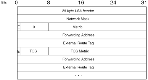
The list that follows describes the fields within the external LSA packet:
- Network Mask— Specifies the network mask of the external network.
- Bit E— Specifies the external type. If set, it is an external Type 2; otherwise, it is Type 1. The difference between type and type external is that the Type 1 metric is similar to the OSPF metric and the cost gets changed every hop; in Type 2, however, the external metric doesn’t change. The metric remains the same throughout the OSPF domain.
-
Forwarding Address— Indicates the address to which data traffic to the advertised network should be forwarded. If the value is set to 0.0.0.0, this means that the traffic should be forwarded to the ASBR. In some situations, the forwarding address will be nonzero, to avoid suboptimal routing. The following list describes events that will produce a nonzero forwarding address:
– OSPF is enabled on the ASBR’s next-hop interface.
– The ASBR’s next-hop interface is nonpassive to OSPF.
– The ASBR’s next-hop interface network type is not point-to-point or point-to-multipoint.
– The ASBR’s next-hop interface address falls into the OSPF network range.
- External Route Tag— Not used by OSPF.
The ToS and ToS Metric fields normally are not used by any vendor.
Example 8-6 shows the output of the external LSA from the Cisco router.
Example 8-6 External LSA Output
RouterE#show ip ospf database external 10.10.10.0
LS age: 954
Options: (No TOS-capability, DC)
LS Type: AS External Link
Link State ID: 10.10.10.0 (External Network Number)
Advertising Router: 141.108.1.21
LS Seq Number: 80000003
Checksum: 0x97D8
Length: 36
Network Mask: /24
Metric Type: 2 (Larger than any link state path)
TOS: 0
Metric: 20
Forward Address: 0.0.0.0
External Route Tag: 0
The output in Example 8-6 shows an external LSA for network 10.10.10.0/24. This is a Type 2 external LSA. There are a few important things to remember here:
- The Link-State ID field represents the external network number.
- The advertising router field contains the router ID of the ASBR.
- Metric Type: 2 means that the metric—20, in this case—remains the same throughout the OSPF domain.
- A forwarding address of 0.0.0.0 means that the traffic should be forwarded directly to the ASBR.
- The route to the nonzero forwarding address must be known through an intra-area or interarea route; otherwise, the external route will not get installed in the routing table.
Figure 8-17 shows a network in which a Type 5 LSA is originated by Router E (ASBR). RIP is getting redistributed into Router E, so Router E originates a Type 5 LSA for every RIP subnet. Those Type 5 LSAs are propagated throughout the OSPF domain.
Figure 8-17. Network Diagram Where ASBR Originates Type 5 LSAs for a RIP Learned Route
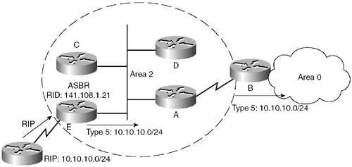
Route 1.0 LAB
Route 1.0 LAB
LAB 1-1 ACCESS SKILL FOR IMPLEMENTING Complex Networks
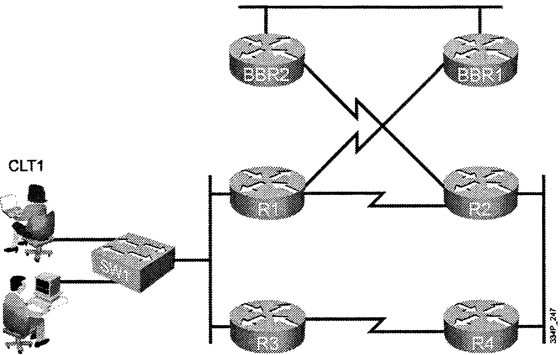
CLT2
目的:
- 確認必須提供的網路需求
- 確認必須的訊息
- 確認實行時需要的工作及建立實施計劃
- 驗證活動
實施政策
- 基礎結構採用 CISCO 的三層式架構:
-
必須滿足的基本要求
- Functionality 在時限內滿足並且支援應用程式及資料流量的需
- Performance 滿足企業對 響應速度,吞吐量,利用率
- Scalability 滿足企業對 人員,應用程式及資料流量未來的可擴展性
- Availability 提供企業網路及應用接近 99.999的可用性
- Cost-effectiveness: 在限定的預算
- Functionality 在時限內滿足並且支援應用程式及資料流量的需
解決方案範例.
- 1-確認必須提供的網路需求& 2. 確認必須的訊息
1.1 使用的應用程式及需要的資料流量
1.2 存在的網路設備,及其作業系統/固件(OS /FirmWare)
1.3 拓樸圖及連線資訊
1.4 IP位址及部署分配
1.5 使用的路由協定及路由器上的設定(注:通常應為所有的網路設備協定)
- 3-確認實行時需要的工作及建立實施計劃
2.1 撰寫必要交件的資訊
2.2 準備必須的工具及資源
連接PC(Terminal)到設備
選擇並且保留必要資源
2.3 設定所有設備上的IP位址
2.4 啟用所有參與運作的界面
2.5 設定網路設備上的必要協定(例:路由協定 )
2.6 設定特定網路設備上的必要特性(例:路由聚合,及封閉網路)
2.7 驗證網路設備及連線是否依據設定正常的運作
2.8 測量執行效率及記錄結果是否滿足
2.9 建立設定備份
2.10建立實施計劃,網路維運基線,及提出必要建議
- 4-驗證活動
3.1 驗證所有設備界面正常運作
3.2 驗證網路設備上的設定是否正運作(例:路由協定)
3.3 驗證網路設備上的路徑是否正確(例:路由表是否包含所有規劃的正確路徑)
3.4 驗證特定網路設備上的必要特性(例:送出聚合路由的路由器是否自我生成指向null0界面的路)
3.5 驗證網路設備上的路徑是否正確及是否要進行調整
END LAB 1-1 ACCESS SKILL FOR IMPLEMENTING Complex Networks
——————————————————————————————————
LAB 2-1 Configure and verify Eigrp Operations
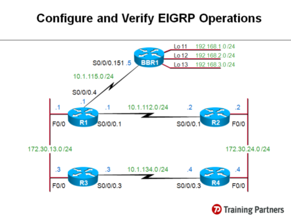
目的:
- 在WAN 和 LAB 的界面上設定基本的EIGRP及驗證其運
- 使用必要的工具及指令進行設定
- 在某一路由器上使用LAN界面上的次要IP位址加入EIGRP路由協定
- 更改EIGRP路徑測量參數來影響路由的選擇
- 最佳化-1.避免EIGRP的界面送出不必要的HELLO封包訊息
- 最佳化-2.避免不必要的小路由被送出,在特定設備上執行路由聚合
- 列出實施行步驟
- 寫下驗證,測試的計劃檢查所有的設定如規劃方式進行運作
- 利用 SHOW 及 DEBUG的指令檢查設定及驗證運作
Note: 以上router的介面名稱可能與您正在使用的Lab有所不同, 請以實際介面名稱為準.
實施政策
1 講師已為您準備好基本的設定 (IP, Frame-Relay Map)
2 進行EIGRP的基本設定:
2.1 設定R1至R4上的所有路由器, 讓所有網路上的Subnet的Route都能互相交換, 包括來自BBR1的Routes.
2.2 EIGRP的設定應該精確, 請確定當有其它網段的 IP被設定到路由器的介面上時, EIGRP不會自動地將此新增的網段(Route)送出.
2.3 網段都應該依照原有的網路與subnet mask長度送出, auto summarization 則應該被disable.
3 EIGRP 設定的確認:
3.1 檢查R1與 BBR1的 Neighbor有正確的建立.
3.2 檢查R1與 R2, R3, R4的 Neighbor有正確的建立.
3.3 檢查Router所送出的route及subnet mask長度正確, 請嘗試用不同的指令查看而不要直接查看topology及routing Table.
3.4 查看R1的topology 與routing table, 你應該學到所有的routes, 請注意每筆route在topology table中的FD值都正確的
反應在routing table Metric 欄位.
3.5 檢查R4的topology與routing table, 請注意, R4應該學到external routes, 並且這些routes都各有兩條不同的路徑.
例如,你將會看到 192.168.1.0/24的route來自兩個不同的neighbor, 而且metric 相同, 由於預設的Equal Cost Load Balancing 的原故, 這兩個路徑都被 install 到 routing table 中.
3 3.6 在R4啟動 EIGRP event debugging, 你應該看到EIGRP封包的交換, 其中包括10.1.112.0/24(介於R1與R2間的網段)這筆route,
在其它router的query R4時, R4的回應中將會含有infinite metric的值(4294967295)
解答範例:
1.檢查各路由器上所有界面的資訊
R1:
P5R1.LAB21#sh ip interface brief | section up
FastEthernet0/0 172.30.13.1 YES NVRAM up up
Serial0/0/0 unassigned YES NVRAM up up
Serial0/0/0.1 10.1.112.1 YES NVRAM up up
Serial0/0/0.4 10.1.115.1 YES TFTP up up
P5R1.LAB21#sh frame-relay pvc | section DLCI
DLCI = 512, DLCI USAGE = LOCAL, PVC STATUS = ACTIVE, INTERFACE = Serial0/0/0.1
DLCI = 513, DLCI USAGE = UNUSED, PVC STATUS = ACTIVE, INTERFACE = Serial0/0/0
DLCI = 514, DLCI USAGE = UNUSED, PVC STATUS = ACTIVE, INTERFACE = Serial0/0/0
DLCI = 515, DLCI USAGE = LOCAL, PVC STATUS = ACTIVE, INTERFACE = Serial0/0/0.4
DLCI = 516, DLCI USAGE = UNUSED, PVC STATUS = ACTIVE, INTERFACE = Serial0/0/0
P5R1.LAB21#sh ip protocols
R2
P5R2.LAB21#sh ip int brief | section up
FastEthernet0/0 172.30.24.2 YES NVRAM up up
Serial0/0/0 unassigned YES NVRAM up up
Serial0/0/0.1 10.1.112.2 YES NVRAM up up
P5R2.LAB21#sh frame-relay pvc | section DLCI
DLCI = 521, DLCI USAGE = LOCAL, PVC STATUS = ACTIVE, INTERFACE = Serial0/0/0.1
DLCI = 523, DLCI USAGE = UNUSED, PVC STATUS = ACTIVE, INTERFACE = Serial0/0/0
DLCI = 524, DLCI USAGE = UNUSED, PVC STATUS = ACTIVE, INTERFACE = Serial0/0/0
P5R2.LAB21#sh ip protocols
R3:
P5R3.LAB21#sh ip interface brief | section up
FastEthernet0/0 172.30.13.3 YES NVRAM up up
Serial0/0/0 unassigned YES NVRAM up up
Serial0/0/0.3 10.1.134.3 YES NVRAM up up
P5R3.LAB21#sh frame-relay pvc | section DLCI
DLCI = 531, DLCI USAGE = UNUSED, PVC STATUS = ACTIVE, INTERFACE = Serial0/0/0
DLCI = 532, DLCI USAGE = UNUSED, PVC STATUS = ACTIVE, INTERFACE = Serial0/0/0
DLCI = 534, DLCI USAGE = LOCAL, PVC STATUS = ACTIVE, INTERFACE = Serial0/0/0.3
P5R3.LAB21#sh ip protocols
R4:
P5R4.LAB21#sh ip interface brief | section up
FastEthernet0/0 172.30.24.4 YES NVRAM up up
Serial0/0/0 unassigned YES NVRAM up up
Serial0/0/0.3 10.1.134.4 YES NVRAM up up
P5R4.LAB21#sh frame-relay pvc | section DLCI
DLCI = 541, DLCI USAGE = UNUSED, PVC STATUS = ACTIVE, INTERFACE = Serial0/0/0
DLCI = 542, DLCI USAGE = UNUSED, PVC STATUS = ACTIVE, INTERFACE = Serial0/0/0
DLCI = 543, DLCI USAGE = LOCAL, PVC STATUS = ACTIVE, INTERFACE = Serial0/0/0.3
P5R4.LAB21#
P5R4.LAB21#sh ip protocols
S1:
P5S1.LAB21.to.LAB61# sh vlan brief
VLAN Name Status Ports
—- ——————————– ——— ——————————-
1 default active Fa0/2, Fa0/4, Fa0/5, Fa0/6
Fa0/7, Fa0/8, Fa0/9, Fa0/10
Fa0/11, Fa0/12, Fa0/13, Fa0/14
Fa0/15, Fa0/16, Fa0/17, Fa0/18
Fa0/19, Fa0/20, Fa0/21, Fa0/22
Fa0/23, Fa0/24, Gi0/1, Gi0/2
111 VLAN0111 active
113 VLAN0113 active Fa0/1, Fa0/3
1002 fddi-default act/unsup
1003 token-ring-default act/unsup
1004 fddinet-default act/unsup
1005 trnet-default act/unsup
P5S1.LAB21.to.LAB61# sh vlan sum
P5S1.LAB21.to.LAB61# sh vlan summary
Number of existing VLANs : 7
Number of existing VTP VLANs : 7
Number of existing extended VLANs : 0
LAB 2-1 Configure and verify Eigrp Operations
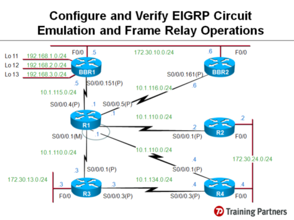
以上router的介面名稱可能與您正在使用的Lab有所不同, 請以實際介面名稱為準.
1 講師已為您準備好基本設定 (IP, Frame-Relay Map)
2 啟動EIGRP 於:
2.1 R1-BBR1 的p2p sub-interface 介面
2.2 R1-BBR2 的p2p sub-interface 介面
2.3 R3-R4 的 p2p sub-interface 介面, 含 LAN 的網段.
2.4 EIGRP 的設定應讓這個Lab所使用的其它子網路一但加入時, 會自動加到 EIGRP 的 Table 中.
3 確定 R1 的 Topology Table 與 Routing Table:
3.1 由 BBR1 學到 192.168.x.0/24
3.2 由 BBR2 學到 172.30.10.0/24
3.3 比對 Topology Table 與 Routing Table 中的Metric 值.
4 啟動 EIGRP 於:
4.1 R1 與 (R2, R3, R4) 間的 Multipoint Sub-interface.
4.2 所有Router 要能交換 Routes.
5 檢查 Neighbor 與 Routing Table:
5.1 R1-R2
5.2 R1-R3
5.3 R1-R4
5.4 Shutdown R3-R4, 檢查 R3此時學不到 172.30.24.0/24
6 調整 R1 的設定:
6.1 讓 R3 與 R4 仍能學到彼此的LAN subnet.
6.2 No shutdown R3-R4 間的介面.
7 檢查 R1-R2, R1-R3, R1-R4:
7.1 Neighbor Table
7.2 Topology Table
7.3 Routing Table
7.4 觀察 Topology Table 與 Routing Table 的 metric 變化.
7.5 再次 shutdown R3-R4 間的介面, 並確認 R2, R4 是從 R1 學到 172.30.13.0/24
8 正確調整參數, 影響路徑的選擇:
8.1 設定R3 與 R4之間介面的 Delay, 讓R2把學自R1的Route當作是Feasible Successor(Backup)
8.2 設定 R3, 讓R3到 172.30.24.0/24 的路徑可執行 Unequal Cost Load Balancing.
8.3 設定正確Route與參數, 讓 R3 到 172.30.24.0/24 的路徑是以 R4作為 Primary Route, 以 R1作為Backup Route.
9 最後, 確定要讓R3的 LAN 要能與 R2, R4 的 LAN 仍然可以建立連線.
TP Lab之設定內容已錄製成為"影音檔" 供學員參考, 請參訪以下任一連結:
(1) TP官方網站:
http://www.training-partners.com.tw , 點選 “技術開講-影音專區"
(2) TP Facebook: facebook.com/group.php?gid=50505115609點選"影片"
LAB 2-3
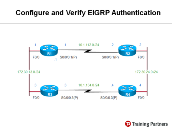
以上router的介面名稱可能與您正在使用的Lab有所不同, 請以實際介面名稱為準.
1 在LAN介面上設定EIGRP Authentication.
1.1 EIGRP Authentication 應使用 安全的機制.
1.2 EIGRP Authentication 的密碼永不過期.
1.3 在所有Router上應用正確的指令檢查 Key Chain 的設定正確無誤, 並且使用正確的key 在作Authentication, 確認 Key 的時間永不過期.
1.4 檢查 EIGRP Neighbor 正確的建立.
1.5 檢查 EIGRP Routing 都有正確學習到每一個Router上.
2 在WAN介面上設定 EIGRP Authentication.
2.1 EIGRP Authentication 應使用 安全的機制.
2.2 EIGRP Authentication 的密碼永不過期.
2.3 在所有Router上應用正確的指令檢查 Key Chain 的設定正確無誤, 並且使用正確的key 在作Authentication, 確認 Key 的時間永不過期.
2.4 檢查 EIGRP Neighbor 正確的建立.
2.5 檢查 EIGRP Routing 都有正確學習到每一個Router上.
LAB 2-4
Implement and Troubleshoot EIGRP Operations
Trouble Ticket A: EIGRP Adjacency Issues
1 您已離開公司一段時間, 在這段時間當中, 有位資淺的工程師替代了您的工作. 由於當時正好有需求要新增額外的 IP 網段於R2與R4之間, 於是那位工程師便設定了額外的 IP網段, 但卻導致在此網段之外的其它網路因而斷線. 你被要求要檢查並更正這個錯誤, 以便讓此新增的網段能夠被存取及使用.
2 另一個問題是有關與BBR1 Router間的 EIGRP Adjacency, 就在你不在的這段時間, 這位資淺的工程師被要求改善與BBR1之間的Routing的安全性, 但是卻導致與BBR1無法建立Adjacency. 你再次被要求更正這個現象.
3 這位工程師也被要求要對EIGRP進行最佳化. 他作了一些設定以便改善R4的Metric計算的數值, 但此舉卻造成與R4之間斷線. 此外, 他企圖在 Routers上用summarization 的設定將Routing進行最佳化, 但卻沒有得到預期的結果, 你也被要求對此進行處理.
4 你的助手向你報告, 連接在R2與R4之間的LAN, 在最近才部署上去的R3上面是看不到的. R3僅有有限的連線. 但在R1上卻可以看到並存取所有的網路. 你必需找出問題並且對其進行更正.
Instructions:
5 你與同伴必需建立 Troubleshooting 與 Verification Plan 並進行分工. Trouble Ticket A 與 B是可以同步進行的. 請將處理的過程記錄於書上的"Troubleshooting Log"以便你能夠據此與同伴進行討論, 並且review整個過程
Routing LAB Hints
ROUTE-LAB
LAB 1-1


目的:
- 確認必須提供的網路需求
- 確認必須的訊息
- 確認實行時需要的工作及建立實施計劃
- 驗證活動
實施政策
- 基礎結構採用 CISCO 的三層式架構:
-
必須滿足的基本要求
- Functionality 在時限內滿足並且支援應用程式及資料流量的需
- Performance 滿足企業對 響應速度,吞吐量,利用率
- Scalability 滿足企業對 人員,應用程式及資料流量未來的可擴展性
- Availability 提供企業網路及應用接近 99.999的可用性
- Cost-effectiveness: 在限定的預算
- Functionality 在時限內滿足並且支援應用程式及資料流量的需
解決方案範例.
- 1-確認必須提供的網路需求& 2. 確認必須的訊息
1.1 使用的應用程式及需要的資料流量
1.2 存在的網路設備,及其作業系統/固件(OS /FirmWare)
1.3 拓樸圖及連線資訊
1.4 IP位址及部署分配
1.5 使用的路由協定及路由器上的設定(注:通常應為所有的網路設備協定)
- 3-確認實行時需要的工作及建立實施計劃
2.1 撰寫必要交件的資訊
2.2 準備必須的工具及資源
連接PC(Terminal)到設備
選擇並且保留必要資源
2.3 設定所有設備上的IP位址
2.4 啟用所有參與運作的界面
2.5 設定網路設備上的必要協定(例:路由協定 )
2.6 設定特定網路設備上的必要特性(例:路由聚合,及封閉網路)
2.7 驗證網路設備及連線是否依據設定正常的運作
2.8 測量執行效率及記錄結果是否滿足
2.9 建立設定備份
2.10建立實施計劃,網路維運基線,及提出必要建議
- 4-驗證活動
3.1 驗證所有設備界面正常運作
3.2 驗證網路設備上的設定是否正運作(例:路由協定)
3.3 驗證網路設備上的路徑是否正確(例:路由表是否包含所有規劃的正確路徑)
3.4 驗證特定網路設備上的必要特性(例:送出聚合路由的路由器是否自我生成指向null0界面的路)
3.5 驗證網路設備上的路徑是否正確及是否要進行調整
LAB 2-1

目的:
- 在WAN 和 LAB 的界面上設定基本的EIGRP及驗證其運
- 使用必要的工具及指令進行設定
- 在某一路由器上使用LAN界面上的次要IP位址加入EIGRP路由協定
- 更改EIGRP路徑測量參數來影響路由的選擇
- 最佳化-1.避免EIGRP的界面送出不必要的HELLO封包訊息
- 最佳化-2.避免不必要的小路由被送出,在特定設備上執行路由聚合
- 列出實施行步驟
- 寫下驗證,測試的計劃檢查所有的設定如規劃方式進行運作
- 利用 SHOW 及 DEBUG的指令檢查設定及驗證運作
Note: 以上router的介面名稱可能與您正在使用的Lab有所不同, 請以實際介面名稱為準.
實施政策
1 講師已為您準備好基本的設定 (IP, Frame-Relay Map)
2 進行EIGRP的基本設定:
2.1 設定R1至R4上的所有路由器, 讓所有網路上的Subnet的Route都能互相交換, 包括來自BBR1的Routes.
2.2 EIGRP的設定應該精確, 請確定當有其它網段的 IP被設定到路由器的介面上時, EIGRP不會自動地將此新增的網段(Route)送出.
2.3 網段都應該依照原有的網路與subnet mask長度送出, auto summarization 則應該被disable.
3 EIGRP 設定的確認:
3.1 檢查R1與 BBR1的 Neighbor有正確的建立.
3.2 檢查R1與 R2, R3, R4的 Neighbor有正確的建立.
3.3 檢查Router所送出的route及subnet mask長度正確, 請嘗試用不同的指令查看而不要直接查看topology及routing Table.
3.4 查看R1的topology 與routing table, 你應該學到所有的routes, 請注意每筆route在topology table中的FD值都正確的
反應在routing table Metric 欄位.
3.5 檢查R4的topology與routing table, 請注意, R4應該學到external routes, 並且這些routes都各有兩條不同的路徑.
例如,你將會看到 192.168.1.0/24的route來自兩個不同的neighbor, 而且metric 相同, 由於預設的Equal Cost Load Balancing 的原故, 這兩個路徑都被 install 到 routing table 中.
3 3.6 在R4啟動 EIGRP event debugging, 你應該看到EIGRP封包的交換, 其中包括10.1.112.0/24(介於R1與R2間的網段)這筆route,
在其它router的query R4時, R4的回應中將會含有infinite metric的值(4294967295)
解答範例:
1.檢查各路由器上所有界面的資訊
R1:
P5R1.LAB21#sh ip interface brief | section up
FastEthernet0/0 172.30.13.1 YES NVRAM up up
Serial0/0/0 unassigned YES NVRAM up up
Serial0/0/0.1 10.1.112.1 YES NVRAM up up
Serial0/0/0.4 10.1.115.1 YES TFTP up up
P5R1.LAB21#sh frame-relay pvc | section DLCI
DLCI = 512, DLCI USAGE = LOCAL, PVC STATUS = ACTIVE, INTERFACE = Serial0/0/0.1
DLCI = 513, DLCI USAGE = UNUSED, PVC STATUS = ACTIVE, INTERFACE = Serial0/0/0
DLCI = 514, DLCI USAGE = UNUSED, PVC STATUS = ACTIVE, INTERFACE = Serial0/0/0
DLCI = 515, DLCI USAGE = LOCAL, PVC STATUS = ACTIVE, INTERFACE = Serial0/0/0.4
DLCI = 516, DLCI USAGE = UNUSED, PVC STATUS = ACTIVE, INTERFACE = Serial0/0/0
P5R1.LAB21#sh ip protocols
R2
P5R2.LAB21#sh ip int brief | section up
FastEthernet0/0 172.30.24.2 YES NVRAM up up
Serial0/0/0 unassigned YES NVRAM up up
Serial0/0/0.1 10.1.112.2 YES NVRAM up up
P5R2.LAB21#sh frame-relay pvc | section DLCI
DLCI = 521, DLCI USAGE = LOCAL, PVC STATUS = ACTIVE, INTERFACE = Serial0/0/0.1
DLCI = 523, DLCI USAGE = UNUSED, PVC STATUS = ACTIVE, INTERFACE = Serial0/0/0
DLCI = 524, DLCI USAGE = UNUSED, PVC STATUS = ACTIVE, INTERFACE = Serial0/0/0
P5R2.LAB21#sh ip protocols
R3:
P5R3.LAB21#sh ip interface brief | section up
FastEthernet0/0 172.30.13.3 YES NVRAM up up
Serial0/0/0 unassigned YES NVRAM up up
Serial0/0/0.3 10.1.134.3 YES NVRAM up up
P5R3.LAB21#sh frame-relay pvc | section DLCI
DLCI = 531, DLCI USAGE = UNUSED, PVC STATUS = ACTIVE, INTERFACE = Serial0/0/0
DLCI = 532, DLCI USAGE = UNUSED, PVC STATUS = ACTIVE, INTERFACE = Serial0/0/0
DLCI = 534, DLCI USAGE = LOCAL, PVC STATUS = ACTIVE, INTERFACE = Serial0/0/0.3
P5R3.LAB21#sh ip protocols
R4:
P5R4.LAB21#sh ip interface brief | section up
FastEthernet0/0 172.30.24.4 YES NVRAM up up
Serial0/0/0 unassigned YES NVRAM up up
Serial0/0/0.3 10.1.134.4 YES NVRAM up up
P5R4.LAB21#sh frame-relay pvc | section DLCI
DLCI = 541, DLCI USAGE = UNUSED, PVC STATUS = ACTIVE, INTERFACE = Serial0/0/0
DLCI = 542, DLCI USAGE = UNUSED, PVC STATUS = ACTIVE, INTERFACE = Serial0/0/0
DLCI = 543, DLCI USAGE = LOCAL, PVC STATUS = ACTIVE, INTERFACE = Serial0/0/0.3
P5R4.LAB21#
P5R4.LAB21#sh ip protocols
S1:
P5S1.LAB21.to.LAB61# sh vlan brief
VLAN Name Status Ports
—- ——————————– ——— ——————————-
1 default active Fa0/2, Fa0/4, Fa0/5, Fa0/6
Fa0/7, Fa0/8, Fa0/9, Fa0/10
Fa0/11, Fa0/12, Fa0/13, Fa0/14
Fa0/15, Fa0/16, Fa0/17, Fa0/18
Fa0/19, Fa0/20, Fa0/21, Fa0/22
Fa0/23, Fa0/24, Gi0/1, Gi0/2
111 VLAN0111 active
113 VLAN0113 active Fa0/1, Fa0/3
1002 fddi-default act/unsup
1003 token-ring-default act/unsup
1004 fddinet-default act/unsup
1005 trnet-default act/unsup
P5S1.LAB21.to.LAB61# sh vlan sum
P5S1.LAB21.to.LAB61# sh vlan summary
Number of existing VLANs : 7
Number of existing VTP VLANs : 7
LAB2-2
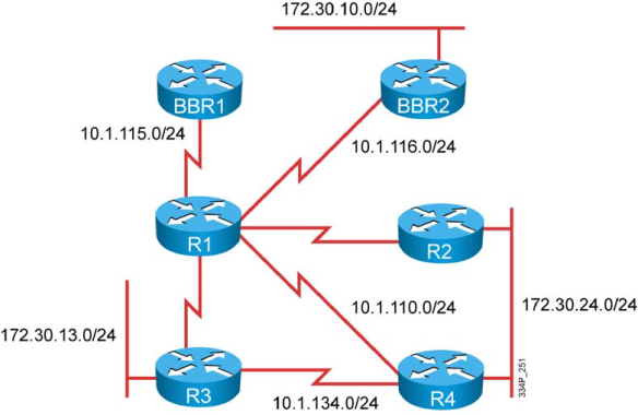
以上router的介面名稱可能與您正在使用的Lab有所不同, 請以實際介面名稱為準.
2.3 R3-R4 的 p2p sub-interface 介面, 含 LAN 的網段.
2.4 EIGRP 的設定應讓這個Lab所使用的其它子網路一但加入時, 會自動加到 EIGRP 的 Table 中.
3 確定 R1 的 Topology Table 與 Routing Table:
3.1 由 BBR1 學到 192.168.x.0/24
3.2 由 BBR2 學到 172.30.10.0/24
3.3 比對 Topology Table 與 Routing Table 中的Metric 值.
4 啟動 EIGRP 於:
4.1 R1 與 (R2, R3, R4) 間的 Multipoint Sub-interface.
4.2 所有Router 要能交換 Routes.
5 檢查 Neighbor 與 Routing Table:
5.1 R1-R2
5.2 R1-R3
5.3 R1-R4
5.4 Shutdown R3-R4, 檢查 R3此時學不到 172.30.24.0/24
6 調整 R1 的設定:
6.1 讓 R3 與 R4 仍能學到彼此的LAN subnet.
6.2 No shutdown R3-R4 間的介面.
7 檢查 R1-R2, R1-R3, R1-R4:
7.1 Neighbor Table
7.2 Topology Table
7.3 Routing Table
7.4 觀察 Topology Table 與 Routing Table 的 metric 變化.
7.5 再次 shutdown R3-R4 間的介面, 並確認 R2, R4 是從 R1 學到 172.30.13.0/24
8 正確調整參數, 影響路徑的選擇:
8.1 設定R3 與 R4之間介面的 Delay, 讓R2把學自R1的Route當作是Feasible Successor(Backup)
8.2 設定 R3, 讓R3到 172.30.24.0/24 的路徑可執行 Unequal Cost Load Balancing.
8.3 設定正確Route與參數, 讓 R3 到 172.30.24.0/24 的路徑是以 R4作為 Primary Route, 以 R1作為Backup Route.
9 最後, 確定要讓R3的 LAN 要能與 R2, R4 的 LAN 仍然可以建立連線.
LAB 2-3
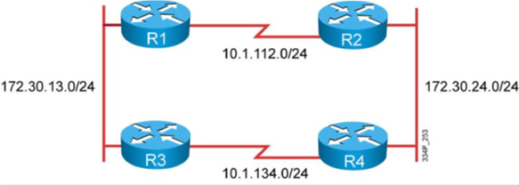
以上router的介面名稱可能與您正在使用的Lab有所不同, 請以實際介面名稱為準.
1 在LAN介面上設定EIGRP Authentication.
1.1 EIGRP Authentication 應使用
安全的機制.
1.2 EIGRP Authentication 的密碼永不過期.
1.3 在所有Router上應用正確的指令檢查 Key Chain 的設定正確無誤, 並且使用正確的key 在作Authentication, 確認 Key 的時間永不過期.
1.4 檢查 EIGRP Neighbor 正確的建立.
1.5 檢查 EIGRP Routing 都有正確學習到每一個Router上.
2 在WAN介面上設定 EIGRP Authentication.
2.1 EIGRP Authentication 應使用
安全的機制.
2.2 EIGRP Authentication 的密碼永不過期.
2.3 在所有Router上應用正確的指令檢查 Key Chain 的設定正確無誤, 並且使用正確的key 在作Authentication, 確認 Key 的時間永不過期.
2.4 檢查 EIGRP Neighbor 正確的建立.
2.5 檢查 EIGRP Routing 都有正確學習到每一個Router上.
LAB2-4

以上router的介面名稱可能與您正在使用的Lab有所不同, 請以實際介面名稱為準.
1 在LAN介面上設定EIGRP Authentication.
1.1 EIGRP Authentication 應使用
安全的機制.
1.2 EIGRP Authentication 的密碼永不過期.
1.3 在所有Router上應用正確的指令檢查 Key Chain 的設定正確無誤, 並且使用正確的key 在作Authentication, 確認 Key 的時間永不過期.
1.4 檢查 EIGRP Neighbor 正確的建立.
1.5 檢查 EIGRP Routing 都有正確學習到每一個Router上.
2 在WAN介面上設定 EIGRP Authentication.
2.1 EIGRP Authentication 應使用
安全的機制.
2.2 EIGRP Authentication 的密碼永不過期.
2.3 在所有Router上應用正確的指令檢查 Key Chain 的設定正確無誤, 並且使用正確的key 在作Authentication, 確認 Key 的時間永不過期.
2.4 檢查 EIGRP Neighbor 正確的建立.
2.5 檢查 EIGRP Routing 都有正確學習到每一個Router上.
———————————————————————————————————————-
LAB3-1
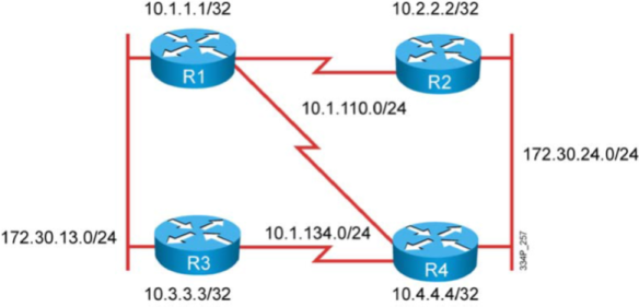
1 設定OSPF於介面上 (R1-R3的LAN, R2-R4的LAN):
1.1 設定OSPF LAN的網段能夠被存取的到.
1.2 所有的Router都在Backbone Area.
1.3 OSPF 的設定應該要精確, 以免當額外的子網段介面加入時自動的啟動了OSPF.
1.4 IP Routing Table 中的網段也應該與實際網路遮罩吻合.
2 確認R1-R3, R2-R4的LAN
2.1 OSPF Neighbor已建立:
2.2 並檢查Neighbor建立的時間有多久?
2.3 是否有任何問題影響Neighbor的溝通? 例如封包在Queue中無法送出?
2.4 在不看Routing Table 與 Topology Table的情況下, 請確定有送出所有LAN與Loopback正確的Route以及正確的 Subnet mask.
2.5 檢查R1的Topology 與 Routing Table進行比較, 你應該看到R3的 Loopback網段及其metric 值.
2.6 確定R1與R3的LAN上是由 R1擔任DR.
3 設定OSPF於WAN介面上(R3-R4)
3.1 R3-R4需交換LAN與Loopback網段.
3.2 OSPF的設定是在 Frame-Relay的Point-to-Point介面上.
3.3 Area 請設定在Backbone Area之內.
3.4 OSPF的設定應該要精確, 以便有額外的IP加入Router時不會自動的被加入OSPF送出.
4 確認R3-R4的WAN
4.1 OSPF Neighbor已建立:
4.2 並檢查Neighbor建立的時間有多久?
4.3 是否有任何問題影響Neighbor的溝通? 例如封包在Queue中無法送出?
4.4 在不看Routing Table 與 Topology Table的情況下, 請確定有送出所有LAN與Loopback正確的Route以及正確的 Subnet mask.
4.5 檢查R1的Topology 與 Routing Table進行比較, 你應該看到R3的 Loopback網段及其metric 值.
5 設定OSPF於WAN介面上(R1-R2, R1-R4)
5.1 OSPF的設定是在 Frame-Relay的Multi-point介面上.
5.2 Area 請設定在Backbone Area之內.
5.3 OSPF的設定應該要精確, 以便有額外的IP加入Router時不會自動的被加入OSPF送出.
6 確認R1-R2, R1-R4的WAN
6.1 OSPF Neighbor已建立:
6.2 並檢查Neighbor建立的時間有多久?
6.3 是否有任何問題影響Neighbor的溝通? 例如封包在Queue中無法送出?
6.4 檢查所有的Router的Topology Table與Routing Table都有學習到所有的Routes及正確的Subnet Mask.
————————————————————————————————————————————-
LAB 3-2
–
1 設定R1-BBR2 WAN 界面上OSPF於(R1-BBR2):
BBR2已經預設為Area 0.
啟動 OSPF 於 R1與BBR2的 WAN介面, 同樣是 Area0.
R1應該由BBR2收到172.30.10.0/24 的網段.
2 確認OSPF的設定(R1-BBR2):
Neighbor 應該已經建立
比對 R1的LSDB與IP Routing Table, 應正確學到Routes.
確定R1的Route可以與172.30.10.0/24網段連線.
3 設定其它OSPF Area (R2, R3, R4):
設定R3的所有介面於 Area 3之中.
設定R2與R4 的所有介面於Area24之中.
檢查所有的Router都應該學習到所有網段的Routes.
4 確認OSPF的設定:
R1與R3應建立Adjacency於Area 3之中.
比對R3的LSDB, Routing Table. R3應正確學到Routes.
R1-R2, R1-R4應建立Adjacency於Area 24之中.
比對R2與R4的LSDB, Routing Table.
R2, R4應正確學到Routes, 包含來自BBR2的subnets.
確定可以正確連到BBR2的172.30.10.0/24 Subnet.
5 調整OSPF參數:
請在Area24中精確的調整Path Cost, 影響運算的結果. 目的是讓R1的172.30.24.0/24 Route是以R2為最佳路徑.
為了讓Area 0更穩定, 請手動指定R1的Router ID.
請在R3上設定讓LAN網段減少不必要的Traffic. 目的是簡省CPU的運算.
6 確認OSPF的設定:
確定所有的Router的OSPF Adjacency 都是 up並且運作正常.
R1應與BBR2在 Area0 中.
R1應與R3在Area3 中.
R1應與R2, R4 在Area24中.
R1應使用新定的Router ID.
R1應使用R2作為前往172.30.24.0/24 做為最佳路徑.
R3應只有與R1建立Adjacency
R3不應透過LAN與R1建立Adjacency.
2. 檢測OSPF的基本設定,運作及目前網路的結構
Rl#show ip ospf neighbor
Rl#show ip ospf database
3. Summarizing the OSPF intemal routes.
R1#
router ospf 1
area 0 range 172.30.0.0 255.255.0.0
4. 1. Use the following example to configure router R3 in this lab:
R3#
router ospf 1
summary-address 192.168.0.0 255.255.0.0
4.2. Verify the OSPF link-state databases and IP routing tables.
R1#show ip ospf database
—————————————————————————————————————————————–
LAB3-3

檢查OSPF (R1-R4)目前的Routes:
R1-R4 都已設定將直接連接的網段以OSPF送出.
R3 已將OSPF External Routes送往你的OSPF網路當中.
檢查OSPF(R1-R4)既有狀態:
檢視R1-R4的設定, 包括涵蓋的network, 啟動的介面, Adjacencies, LSDB與OSPF的Area.
確定R1-R4都可以連到(Ping) 其所學到的每一個網段.
查看Routing Table, 寫下目前的各Router送出的Routes.
設定OSPF Internal Routes 的 Summarization:
根據前面收集的資訊, 進行Routes Summarization的設定.
你需要將來自BBR2的 172.30.x.0/24 Routes進行Summary.
確認OSPF Summarization的設定:
確定 R1-R4的Adjacency仍然正常.
檢查 172.30.x.0/24 經過 Summary 之後的Routes 資訊存在於R1-R4的LSDB 與Routing Table中.
確定各Router都能連線到(Ping)172.30.x.0/24 的IP.
進一步設定OSPF External Routes 的 Summarization:
R3目前已將192.168.x.0/24 的Routes 以 Redistribute的方式送入OSPF之中, 由於R3是這些網段的唯一來源, 因此沒有必要讓其它Router一一學習到每一筆192.168.x.0的Route. 但是, 未來還有可能會有192.168.x.0/24的網段會加入R3.
請設定將192.168.x.0/24 的Routes 進行 Summarization.
確認OSPF Summarization的設定:
確定 R1-R4的Adjacency仍然正常.
檢查 192.168.x.0/24 Summary 之後的Route 資訊存在於R1-R4的LSDB 與Routing Table中.
確定各Router都能連線到(Ping)192.168.x.0/24 的IP.
1.
2.
3.
3. Summarizing the OSPF intemal routes.
3. 1. Use the following example to configure router Rl in this lab:
R 工#
router ospf 1
area 0 range 172.30.0.0 255.255.0.0
3之Veri有T the OSPF link-state databases and IP routing tables.
Rl#show ip ospf database
OSPF Router with ID (1.1.1.1) (process ID 1)
4. Summarizing OSPF extemal routes.
4. 1. Use the following example to configure router R3 in this lab:
R3#
router ospf 1
summary-address 192.168.0.0 255.255.0.0
4.2. Verify the OSPF link-state databases and IP routing tables.
R1#show ip ospf database
————————————————————————————————————————–
LAB 3-4

檢查OSPF (R1-R4)目前的Routes及 網路結構
R1-R4 都已設定將直接連接的網段以OSPF送出.
R3 同時也已將OSPF External Routes送往你的OSPF網路當中.
檢查OSPF(R1-R4)既有狀態:
檢視R1-R4的設定, 包括所涵蓋的OSPF範圍, 啟動的介面, Adjacencies, LSDB與OSPF的Area.
確定R1-R4都可連接到OSPF送出的每一個網段.
查看Routing Table, 記錄目前的各Router送出的Routes與IP定址.
設定OSPF Area 24 的 Area Type:
在R2與R4沒有足夠的CPU與Memory來處理來大量Routing Information. 因此必需設法降低R2與R4上的OSPF Link-State Database大小來節省資源的使用.
確認OSPF的設定:
確認R1與 R2, R3, R4, BBR2都有建立 Adjacency.
確認 R2 與 R4之間有建立 Adjacency.
檢查 R1 與 R3的LSDB, 確定它們都有每一筆OSPF internal 與 external 資訊, 且都有將正確的最佳路徑置入Routing Table.
檢查 R2 與 R4的LSDB有變得較小, 因它們不再擁有每一筆來自External 的網段的資訊, 也就是那些被Redistributed 進入 OSPF的Routes.
確定即使 R2 與 R4 沒有每一筆資訊的細節, 但仍然可以與External Routes的網段連線.
設定 OSPF Area 24 的 Area Type:
在前一個步驟中, 雖然已降低了Area 24 的LSDB的資訊數量以節省R2, R4的資源使用, 但你發現它們仍然無法處理所有OSPF的資訊. 因此, 需要進一步降低OSPF的資訊數量, 可是還是要維持讓R2 與 R4可以連線到每一個網段.
確認OSPF 的設定:
確認R1與 R2, R3, R4, BBR2都有建立 Adjacency.
確認 R2 與 R4之間有建立 Adjacency.
檢查 R1 與 R3的LSDB, 確定它們都有每一筆細節的OSPF internal 與 external 資訊, 且都有將正確的最佳路徑置入Routing Table.
檢查 R2 與 R4的LSDB有變得比較小, 因為它們不再擁有每一筆來自Area 24 以外的網段的資訊, 換言之就是那些被Redistribute 進入 OSPF的Routes以及其它Area的Routes.
確定即使 R2 與 R4 沒有每一筆資訊的細節, 但仍然可以與External Routes的網段
與其它的Area連線.
設定 OSPF Area 3 的 Area Type:
此步驟中將透過設定降低 Area 3 內的資訊數量.
你發現R3沒有足夠的記憶體來儲存所有的OSPF IP Routing 資訊, 換言之, 無法儲存任何動態學到的Routing 資訊.
確認OSPF 的設定:
確認R1與 R2, R3, R4, BBR2都有建立 Adjacency.
確認 R2 與 R4之間有建立 Adjacency.
檢查 R1的LSDB, 確定它們都有每一筆細節的OSPF internal 與 external 資訊, 且都有將正確的最佳路徑置入Routing Table.
確定 R1 可以連接所有學習到的網段.
檢查 R2 與 R4有來自Area 24 internal的Route, 但沒有Area24以外的網段的資訊. 即便如此, R2與R4 仍可連接每一個網段.
檢查 R3的Database並確認其Size變小了, Database 應該有Area3內部的資訊及Redistribute進入Area 3 的資訊, 但沒有任何來自其它Area的資訊或從其它Area 進來的 External Route.
確定 R3 可以連線到每一個網段.
1.
2.
Rl#
router ospf 1
area 24 stub
R2#
router ospf 1
area 24 stub
R4#
router ospf 1
area 24 stub
3.
4.
Use the following examplc to configure routcr R 1 in this lab:
R1#
router ospf 1
area 24 stub no-summary
5.
6.
5.1. Use the following example to configure router R1 in this lab:
R1#
router ospf 1
area 3 nssa no-summary
R3#
router ospf 1
area 3 nssa
7.
—————————————————————————————————————————–
LAB 3-5

檢視網路目前的設定:
1 檢查Routing的設定與動作是否正常.
2 R1, R2, R3, R4目前應已設定OSPF並將它們直連的網段送出.
3 部份Router同時還送出一些External OSPF network 到OSPF的routing domain中.
網路管理員必需在Router上進行設定來防止Traffic被駭客侵入並製造Routing的黑洞, 因此:
1 請以per-interface設定OSPF Authentication於Area 3 與 Area24 的Router上.
2 於 R3-R1間使用Simple OSPF Authentication 並查看其動作過程.
3 於 R2-R4間的LAN使用較安全的 OSPF Authentication 並查看其動作過程.
由於使用最小的指令在下列OSPF AREA的所有界面設定較安全的 OSPF驗證:
1 在Area 24上設定Secure的OSPF Authentication驗證.
2 請確定Authentication成功, LSDB, Routing Table 學習正確.
- 在所有的路由器上用下列指令記錄目前的 OSPF設定
Rx# show ip ospf
RX#show ip ospf databae
RX#show ip route [ospf ]
RX#show ip ospf neighbor
- 在 R1,R3 的OSPF 路由器上 ,針對WAN連結不同OSPF路由器的界面配置簡單密碼驗證 ,密碼為CISCO
在 R2,R4 的OSPF 路由器上 ,針對WAN連結不同OSPF路由器的界面配置較安全的md5驗證 ,ID及key為 1及CISCOR1#
interface SerialO/0/0.2 point-to-point
ip ospf authentication
ip ospf authentication-key CISCO
R2#
interface FastEthernetO/O
ip ospf authentication message-digest
ip ospf message-digest-key 1 md5 CISCO
R3#
interface SerialO/0/0.2 point-to-point
ip ospf authentication
ip ospf authentication-key CISCO
R4#
interface FastEthernetO/O
ip ospf authentication message-digest
ip ospf message-digest-key 1 md5 CISCO
-
驗證R1-R4在驗證後用
Rx# show ip ospf
RX#show ip ospf databae
RX#show ip route [ospf ]
RX#show ip ospf neighbor
令觀察的狀態和未驗證之前相同
LAB 4-1

基本設定
- 在R1與R3之間設定RIPv2路由協定,並且宣告R3的區域網路網段,RIPv2只在廣域網路上交換更新訊息 .
- 在R1, R2 與 R4之間設定 OSPF.路由協定,R1的OSPF路由執行程序只包含連結到 R2,R4的廣域網路界面,
而R2,R4則除了連結R1的廣域網路亦包含了區域網路.
- 在R1 與 BBR2之設定EIGRP路由協定.
- 確認R1與R3之間的RIPv2已啟動, 且R1可以存取由RIPv2學到的網段.
- 確認R1與BBR2之間的EIGRP已啟動, 且R1收到由BBR2送出的EIGRP Routes, 並且可以存取這些網段.
- 確認R1, R2與R4之間的OSPF已啟動, Adjacency已建立, 而且R1可從LAN Segment上的R2與R4學到Routes.同時 R1也可以存取這些網段.
單向Redistribution(RIP-to-EIGRP) 設定:
- 在R3上僅將目前存的Loopback上的網路以重分配(redistribution)的方式加入RIPv2 路由協定,將網段送出.
(限制:不可使用ACL及Route-Map 進行設定->Distribute with prefix-list)
- 在R1上設定RIP-to-EIGRP 的redistribution與filter, 目的是只讓其中一段Loopback(192.168.1.0/24)轉入EIGRP協定
(不可使用Distribute-List.->Route-map with ACL )
- 由於RIP-to-EIGRP是單向將RIP的route轉換為EIGRP, 因此你必需在R3上設定一筆靜態預設路由(Static Default Route)
以提供能夠連線到其它網路的能力.
單向Redistribution(RIP-to-EIGRP) 設定驗證檢查::
- 檢查R1與R3上的RIPv2 Database, 確定R3的Loopback網段在Redistribution後已出現.
- 在R3上再新增一個Loopback介面, 確定這個新增的介面不會自動被Redistribution進入RIPv2的Database中.
R1也不應收到這個訊息.
- 確定 R3可以連線到BBR2的區域網路LAN.
在R1上設定OSPF vs EIGRP双向Redistribution(及 OSPF vs RIP):
- 在適當的Router上設定OSPF與RIP的双向Redistribution.
- RIP 僅接受原來由OSPF路由協定產生的路由進行重分配至RIP的路由協定中
- OSPF僅接受原來由RIP路由協定產生的路由進行重分配至OSPF的路由協定中
在R1上設定OSPF vs EIGRP双向Redistribution(及 OSPF vs RIP)驗證檢查
- 檢查R3上RIP的Routing Table, 應可以看到來自OSPF網域的網段.
- 檢查R1上EIGRP的Topology Table, 應可看到來自OSPF網域的網段.DEX的routes
- 檢查R2與R4的OSPF LSDB 與 Routing Table, 應可看到從RIP與EIGRP網域中Redistribution進來的Routes.
- 確定可以從R2的LAN連接到BBR2的LAN.
- 確定可以從R3的LAN 連接到R2 的LAN.
Solution
1.在R1&R3 啟動 RIP 路由協定
Rl#
router rip
version 2
network 10.0.0.0
no auto-summary
R3#
router rip
version 2
network 10.0.0.0
network 172.30.0.0
no auto-summary
2.驗證RIP路由協定確運作.
驗證 RIP的指令
RX# show ip rip database
RX# show ip route [RIP]
3.在R1&R2&R4 啟動 OSPF 路由協定
R1#
interface SerialO/0/0.1 multipoint
ip ospf network point-to-multipoint
ip ospf hello-interval 10
router ospf 1
log-adjacency-change
network 10.1.110.0 0.0.0.255 area 0
R2#
interface serialO/0/0.1 multipoint
ip ospf network point-to-multipoint
ip ospf hello-interval 10
router ospf 1
log-adjacency-changes
network 10.1.110.0 0.0.0.255 area 0
network 172.30.24.0 0.0.0.255 area 0
R4#
interface serialO/0/0.1 multipoint
ip ospf network point-to-multipoint
ip ospf hello-interval 10
router ospf 1
log-adjacency-changes
network 10.1.110.0 0.0.0.255 area 0
network 172.30.24.0 0.0.0.255 area 0
在R1&R2&R4 驗證 OSPF 路由協定
驗證OSPF的指令
RX#show ip ospf interface
RX#show ip ospf neighbor
RX#show ip ospf database
RX#show ip route
3.在R1啟動 eigrp 路由協定
R1#
router eigrp 1
network 10.l.l16.0 0.0.0.255
在R1驗證 EIGRP 路由協定
驗證 EIGRP的指令
RX#show ip eigrp interface
RX#show ip eigrp neighbor
RX#show ip eigrp toplogy
RX#show ip route
4.(Redistribute CONNECTED)重分配指定的直連界面到 RIP 路由協定
利用 Prefix-list限制重分配的直連界面的網路
ip prefix-list PL-R1P seq 5 permit 192.168.1.0/24
ip prefix-list PL-R1P seq 10 permit 192.168.2.0/24
ip prefix-list PL-R1P seq 15 permit 192.168.3.0/24
R3#
router rip
redistribute connected
distribute-list prefix PL-RIP out connected
R1#重分配指定的RIP路由到 eigrp 路由協定
router eigrp 1
redistribute rip route-map RM-RIP
default-metric 1500 100 255 1 1500
!設定轉入 EIGRP路由的 seed metrics
ip access-list standard ACL-R工P
permit 192.168.2.0 0.0.0.255
permit 192.168.3.0 0.0.0.255
!
route-map RM-RIP deny 10
match ip address ACL-RIP
route-map RM-R1P permit 99
7.在R3上設定預設路由
R3#
ip route 0.0.0.0 0.0.0.0 10.1.113.1
8. 在R1上設定OSPF vs EIGRP双向Redistribution
R1#
router eigrp 1
redistribute ospf 1
router ospf 1
redistribute eigrp 1 subnets
9.在R1上設定OSPF vs RIP 双向Redistribution
R1#
router ospf 1
redistribute rip subnets
router rip
redistribute ospf 1
________________________________________________________________________________________________________________________________________
LAB 5-1

在R1-R4上將所有的界面(LANs ,WANs 及 loopbacks)加入EIGRP 1 的路由協定並檢查其運作
測試由SW上送到 192.168.1.0 及 192.168.2.0的路徑,及是否可到達192.168.1.0 及 192.168.2.0
測試由R1上送到 192.168.3.0 的路徑,及是否可到達192.168.3.0
在R3上更改路徑決定政策,將由來源為 SW上的IP 位址(172.30.13;11)送往192.168.1.0及192.168.2.0時
使用 R1當作下一站位址 (path R3->R1->R2->R4)
驗證R3的決策性路由是否正確運作
在R1上更改路徑決定政策,將R1本身產生的資料流量送往192.168.3.0使用 R3當作下一站位址 (path R1->R3->R4)
STEP1
Rl#
router eigrp 1
network 10.0.0.0
network 172.30.0.0
no auto-sumrnary
R2#
router eigrp 1
network 10.0.0.0
network 172.30.0.0
no auto-summary
R3#
router eigrp 1
network 10.0.0.0
network 172.30.0.0
no auto-summary
R4#
router eigrp 1
network 10.0.0.0
network 172.30.0.0
network 192.168.0.0 0.0.255.255
no auto-summary
STEP2
show ip route & ping
STEP3
在R3上設定 POLICY-BASE ROUTING
Use the following example to configure PBR on router R3 in the lab.
R3#
interface FastEthernetO/O
ip policy route-map RM-PBR
ip access-listextended ACL-PBR
permit ip host 172.30.13.11 192.168.1.0 0.0.0.255
permit ip host 172.30.13.11 192.168.2.0 0.0.0.255
route-map RM-PBR permit 10
match ip address ACL-PBR
set ip next-hop 172.30.13.1
驗證the traffic flow from switch SWl and PBR on R3.
Examine the path of the IP packcts.
timeout is 2 seconds:
sw1#ping 192.168.1.1
Type escape sequence to abort.
Sending 5 , 100-byte ICMP Echos to 192.168.1.1 ,
!!!!!
Success rate is 100 percent (5/5) , round-trip min/avg/max = 58/58/59 ms
timeout is 2 seconds:
R3#debug ip policy
policy routing debugging is on
Note Enable debugging in order to see the policy macth following the ping commands on pod
sw1#ping 192.168.1.1
Type escape sequence to abort.
sending 5 , 100-byte 工CMP Echos to 192.168.1.1 , timeout is 2 seconds:
!!!!!
Success rate is 100 percent (5/5) , round-trip min/avg/max = 51/58/67 ms
R3#
*May 24 14:14:49.025: IP: s=172.30.13.11 (FastEthernetO/O) , d=192.168.1.1 , len
100, FIB policy match
*May 24 14:14:49.025: IP: s=172.30.13.11 (FastEthernetO/O) , d=192.168.1.1 , len
100 , policy match
*May 24 14:14:49.025: IP: route map RM-PBR, item 10 , permit
*May 24 14:14:49.025: IP: s=172.30.13.11 (FastEthernetO/O) , d=192.168.1.1
(FastEthernetO/O) , len 100, policy routed
sw1#ping 192.168.3.1
Type escape sequence to abort.
Sending 5 , 100-byte 工CMP Echos to 192.168.3.1 , timeout is 2 seconds:
!!!!!.
8uccess rate is 100 percent (5/5) , round-trip min/avg/max = 50/57/59 ms
R3#
*May 24 14:15:16.645: IP: s=172.30.13.11 (FastEthernetO/O) , d=192.168.3.1 , len
100 , FIB policy rejected(no match) – normal forwarding
*May 24 14:15:16.645: IP: s=172.30.13.11 (FastEthernetO/O) , d=192.168.3.1
(FastEthernetO/O) , 1en 100 , po1icy rejected – norma1 forwarding
在R1上定義決策性路由影響本身產生流量的傳送路徑
ip local policy route-map RM-LOCAL-PBR
!
ip access-list extended ACL-LOCAL-PBR
permit ip any 192.168.3.0 0.0.0.255
!
route-map RM-LOCAL-PBR permit 10
match ip address ACL-LOCAL-PBR
set ip next-hop 172.30.13.3
. 驗證Verify the traffic flow and PBR on Rl.
R1#ping 192.168.3.1
Type escape sequence to abort.
Sending 5 , 100-byte ICMP Echos to 192.168.3.1 , timeout is 2 seconds:
!!!!!.
Success rate is 100 percent (5/5) , round 咀trip min/avg/max = 56/57/60 ms
R1#traceroute 192.168.3.1
Type escape sequence to abort.
Tracing the route to 192.168.3.1
1 172.30.13.3 0 msec 0 msec 0 msec
2 172.30.13. 工36 msec 32 msec 32 msec
3 10.1.112.2 28 msec 28 msec 28 msec
4 172.30.24.4 28 msec 28 msec *
R1#debug ip po1icy
Po1icy routing debugging is on
Note:Enable debugging in order to see the policy match following the ping commands on pod
router R1
R1#ping 192.168.3.1
Type escape sequence to abort.
Sending 5 , 100-byte ICMP Echos to 192.168.3.1 , timeout is 2 seconds:
!!!!!.
Success rate is 100 percent (5/5) , round-trip min/avg/max = 56/58/60 ms
!
R1#
*May 24 14:28:08.341: IP: s=10.1.112.1 (loca1) , d=192.168.3.1 , 1en 100 , po1icy
match
*May 24 14:28:08.341: IP: route map RM-LOCAL-PBR , item 10 , permit
*May 24 14:28:08.341: IP: s=10.1.112.1 (loca1) , d=192.168.3.1
(FastEthernetO/O) , 1en 100 , po1icy routed
*May 24 14:28:08.341: IP: local to FastEthernetO/O 172.30.13.3
*May 24 14:28:08.401: IP: s=10.1.112.1 (local) , d=192.168.3.1 , len 100 , policy
match
*May 24 14:28:08.401: IP: route map RM-LOCAL-PBR , item 10 , permit
*May 24 14:28:08.401: IP: s=10.1.112.1 (local) , d=192.168.3.1
(FastEthernetO/O) , len 100 , policy routed
*May 24 14:28:08.401: IP: 1ocal to FastEthernetO/O 172.30.13.3
*May 24 14:28:08.457: IP: s=10.1.112.1 (local) , d=192.168.3.1 , len 100 , policy
match
*May 24 14:28:08.457: IP: route map RM-LOCAL-PBR, item 10 , permit
*May 24 14:28:08.457: IP: s=10.1.112.1 (local) , d=192.168.3.1
(FastEthernetO/O) , len 100 , policy routed
*May 24 14:28:08.457: IP: local to FastEthernetO/O 172.30.13.3
*May 24 14:28:08.517: IP: s=10.1.112.1 (local) , d=192.168.3.1 ,len 100, policy
Match
R1#ping 192.168.1.1
Type escape sequence to abort.
Sending 5 , 100-byte ICMP Echos to 192.168.1.1, timeout is 2 seconds:
! ! ! ! !
Success rate is 100 percent (5/5) ,言。und-trip min/avg/max = 56/56/60 ms
R1#
*May 24 14:28:18.977: IP: s=10.1.112.1
rejected — normal forwarding
*May 24 14:28:19.033: 工P: s=10 .1. 112.1
———————————————————————————————————
LAB 6-1 & 6-2 BGP

TASK1
- 在 R1-R4 上 設定及啟用 BGP 協定
- R3 加入 BGP AS 130 ,R1 加入 BGP AS 100 ,並且在 R3 & R1 之間建立 EBGP 的 PEER 關係
- R3 加入 BGP AS 130 ,R4 加入 BGP AS 400 ,並且在 R3 & R4 之間建立 EBGP 的 PEER 關係
- R2加入 BGP AS 200 並和,在AS 100 的R1 加入 之間建立 EBGP 的 PEER 關係
- 在 AS200 的R2 和 加入 BGP AS 400的 R4 之間 建立 EBGP 的 PEER 關係
- 在 AS 130 ,100,400之間的peer 需使用 MD5 進行驗證以達到最安全的交換訊息方式
-
驗證所有 PEER 正確建立鄰居,及接收BGP路由更新訊息
SOL:
STEP 1: 在 R1-R4 使用 show ip int brief | section up 找出所有使用中的界面及IP位址
STEP 2 : 設定基本 BGP PEER關係
R1#
router bgp 100
no synchronization
bgp log-neighbor-changes
ne 工ghbor 10.1.112.2 remote-as 200
neighbor 10.1.113.3 remote-as 130
neighbor 10.1.113.3 password cisco
no auto-summary
R2#
router bgp 200
no synchronization
bgp log-neighbor-changes
neighbor 10.1.112.1 remote-as 100
neighbor 10.1.124.4 remote-as 400
no auto-summary
R3#
router bgp 130
no synchronization
bgp log-neighbor-changes
neighbor 10.1.113.1 remote-as 100
neighbor 10.1.113.1 password cisco
neighbor 10.1.134.4 remote-as 400
neighbor 10.1.134.4 password cisco
no auto-summary
R4#
router bgp 400
no synchronization
bgp log-neighbor-changes
neighbor 10.1.124.2 remote-as 200
neighbor 10.1.134.3 remote-as 130
neigrilior 10.1.134.3 password cisco
no auto-summary
STEP3:驗證
在 R1-R4 上 使用
Rx# Show ip bgp summary
Rx# Show ip bgp neighbor
的指令檢查是否鄰居正確建立
TASK2
- R3利用 NETWORK 指令 宣告直連的網路 172.30.13.0/24 給之前建立的EBGP 鄰居
- R3 利用 REDISTRIBUT 的方式宣告 本身的 loop Back界面給 10.3.3.3/32 給PEER AS 100, 及 400
- 設定 R2 宣告 192.168.x.0的 網路 給鄰居的 AS, 除了宣告各別的192.168.x.0 /24 之外只要有任合
一筆 192.168.x.0/24存在就只送出 192.168.0.0/16 的聚合網路
- 檢查 R1,R2,R4 是否有 172.30.13.0/24 , 10.3.3.3/32 的路由存在 ,且 R1,R3,R4 上是否有192.168.0.0/16 的路由存在(Routing Table & BGP TABEL)
Step 4 宣告BGP的網路
R3# router bgp 130
network 172.30.13.0 mask 255.255.255.0
redistribute connected route-map RM-BGP
!
ip access-l工ststandard ACL-BGP permit 10.3.3.3
!
route-map RM-BGP permit 10 match ip address ACL-BGP
R2#
router bgp 200
network 192.168.1.0
network 192.168.2.0
network 192.168.3.0
aggregate-address 192.168.0.0 255.255.0.0 summary-only
STEP 5 路由表及 BGP table驗證
在 R1,R2,R4 使用 Rx# Show ip bgp 及 sh ip route 的指令進行驗證 172.30.13.0/24 及 10.3.3.3/32 存在與否
在 R1,R3,R4 使用 Rx#show ip bgp 及 s hip route 的指令進行驗證 192.168.0.0/16是否存在
LAB 6-2 BGP
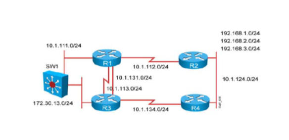
各設備加入的 AS號碼

AS130 和 AS 100 建立 BGP PEER (R3-R1)
AS200 和 AS 100 建立 BGP PEER(R2-R1)
AS400 和 AS 200 建立 BGP PEER(R4-R2)
R3宣告172.30.13.0 /24資訊給 PEER 的 AS
R2宣告192.168.1.0 /24,192.168.2.0/24 ,192.168.3.0/24 資訊給 PEER 的 AS
更改BGP的預設選擇路徑的方式,封包由AS103送往AS200時將使用經由 10.1.131.1的路徑將被當成主要路徑,
10.1.113.1的路徑為次要路徑
建立額外的BGP PEER
SW1加入AS130 和在AS 100的R1建立 E-BGP SESSION
在AS130 的R3 和在AS 400的 R4建立 E-BGP SESSION
在AS130 的 R3和 SW 建立 i-BGP SESSION
移除AS130 R3 和 AS100 R1之間的 E-BGP PEER
檢查 EBGP 的 PEER 關係 ,及路由表中存在需要的路由 ,以及AS130的主要傳送及接收路徑
影響來自AS200 進入 AS130的路徑將偏好使用R1
SOL:
STEP1:建立基本BGP peer
R1#
router bgp 100
no synchronization
bgp log-neighbor-changes
neighbor 10.1.112.2 remoteas200
! TO R2
neighbor 10.1.113.3 remote-as 130
! TO R3
neighbor 10.1.131.3 remote-as 130
! TO R3
no auto-summary
R2#
router bgp 200
no synchronization
bgp log neighbor-changes
neighbor 10.1.112.1 remote-as 100
! TO R1
neighbor 10.1.124.4 remote-as 400
! To R4
no auto-summary
R3#
router bgp 130
no synchronization
bgp log-neighbor-changes
neighbor 10.1.113.1remote-as 100
! To R1
neighbor 10.1.131.1 remote-as 100
! To R1
no auto-summary
R4#
router bgp 400
no synchronization
bgp log-neighbor-changes
neighbor 10.1.124.2 remote-as 200
! TO R2
no auto-summary
STEP2:
RX# show ip bgp summary
RX# show ip bgp
STEP 3 宣告網路
R2#
router bgp 200
network 192.168.1.0
network 192.168.2.0
network 192.168.3.0
R3#
router bgp 130
network 172.30.13.0 mask 255.255.255.0
STEP4
RX# show ip bgp
RX# show ip route
STEP 5修正路徑
R3#
router bgp 130
neighbor 10.1.113.1 route-map RM-MED out
!影響返回的路徑,用10.1.131,1當作較佳路徑
neighbor 10.1.131.1 route-map RM-WEIGHT in
!影響傳送路徑使用10.1.131.1當作主要傳送路徑
route-map RM-WEIGHT permit 10
set weight 1000 route-map RM-MED permit 10
route-map RM-MED permit 10
set metric 1000
EIGRP Intrduce
|


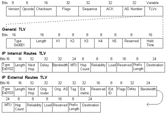
Iscsi mpio
在ESXi 5.0之前的版本中,要想實現完整的iSCSI MPIO(容錯/負載均衡),需要通過複雜的命令列才能實現。
在ESXi 5.0中,可以通過圖形管理介面來簡單的實現。
步驟:
1 首先,新增一個iSCSI-1 VMKernel (同時會新建一個vSwitch2),(本案例使用vmnic2/vmnic3兩張物理網卡)
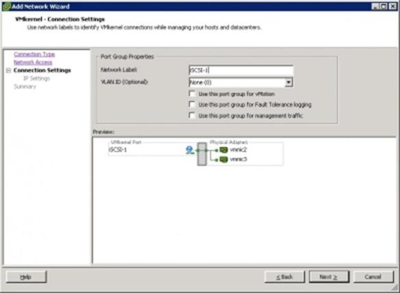
9-27-2011 17:27:22 上传
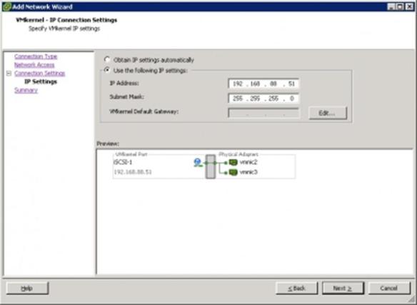
9-27-2011 17:27:23 上传
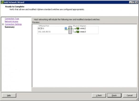
9-27-2011 17:27:24 上传
2 在vSwitch2中,再添加一個iSCSI-2 VMKernel
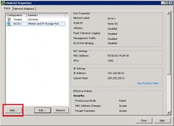
9-27-2011 17:27:25 上传
然後會得到這樣一個配置的vSwitch2
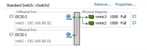
9-27-2011 17:27:26 上传
3 在vSwitch2中,編輯iSCSI-1 VMKernel的屬性,在NIC Teaming下的Override switch failover order處打上勾,
然後將vmnic2設為Active Adapters, vmnic3設為Unused Adapters
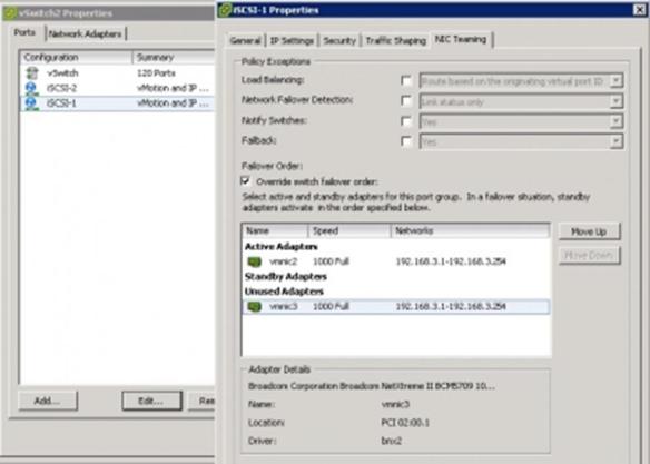
9-27-2011 17:27:28 上传
同樣的方法編輯iSCSI-2 VMKernel的屬性,在NIC Teaming下的Override switch failover order處打上勾,
這裡要注意,要將vmnic3設為Active Adapters, vmnic2設為Unused Adapters
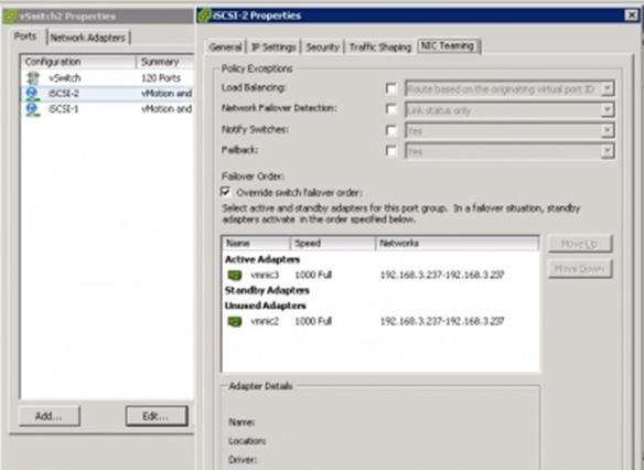
9-27-2011 17:27:29 上传
到此,iSCSI VMKernel設置完成。
4 創建Software iSCSI Adapter(iSCSI Initiator)
在ESXi 5.0中,默認是不存在Software iSCSI Adapter的,沒關係,可以在Storage Adapter中創建一個
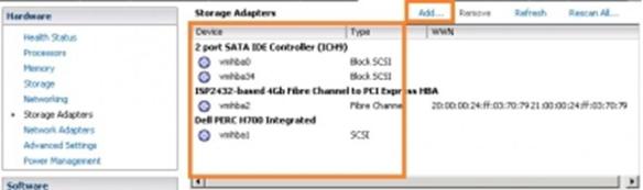
9-27-2011 17:27:12 上传
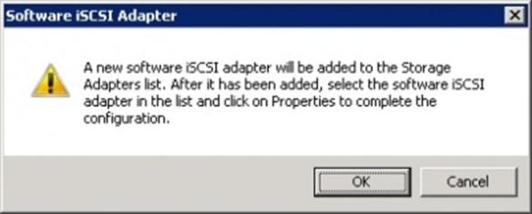
9-27-2011 17:27:21 上传
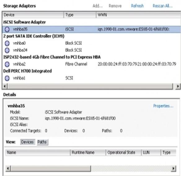
9-27-2011 17:27:21 上传
5 然後在iSCSI SAN中給予此iSCSI Initiator訪問共用vmfs lun的存取權限。
然後在此Software iSCSI Adapter(vmhba35)的屬性中設置iSCSI LUN的連結。
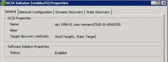
9-27-2011 17:27:30 上传
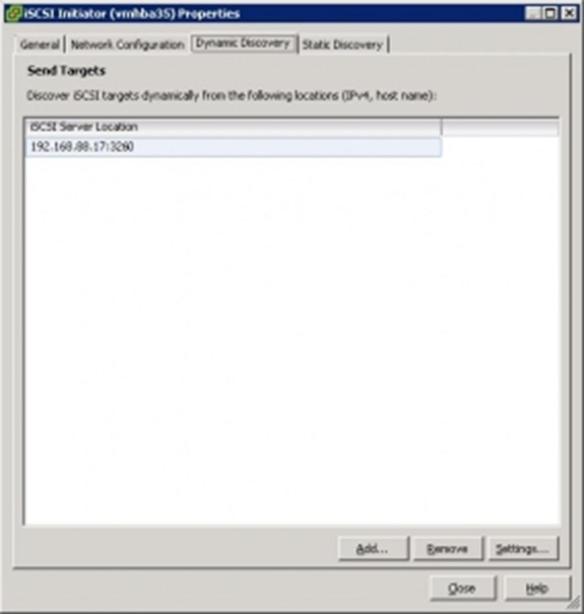
9-27-2011 17:27:31 上传
6 在Software iSCSI Adapter(vmhba35)的屬性中設置Network Configuration,將 iSCSI-1和 iSCSI-2加入到其中
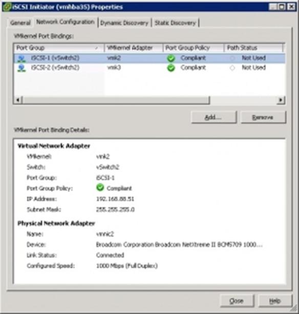
9-27-2011 17:27:32 上传
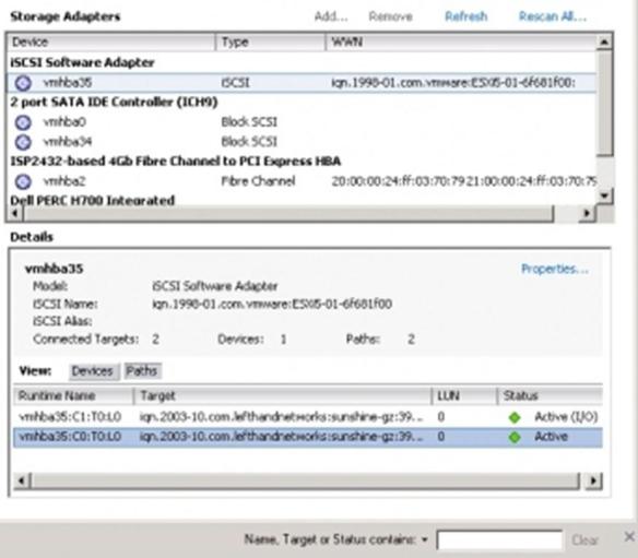
9-27-2011 17:27:33 上传
然後Rescan All Storage … 添加上分配的LUN, 這是可以看到Patch Status由原來Not used變為了Active.
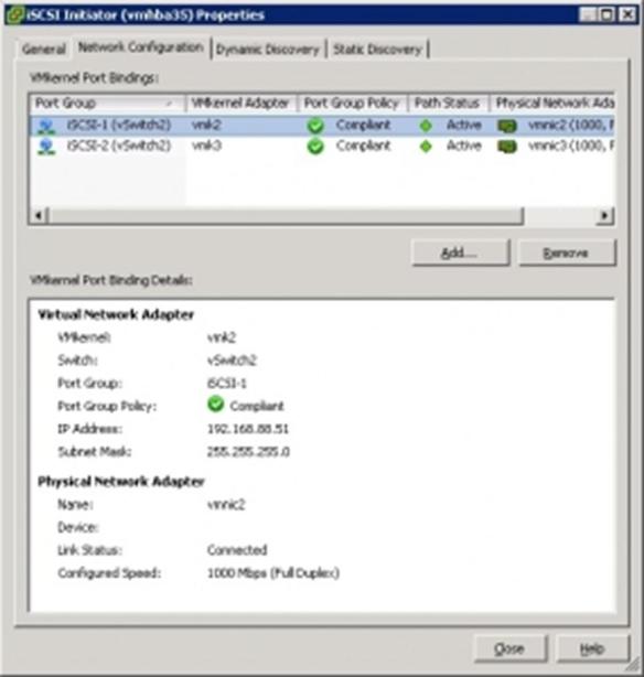
9-27-2011 17:27:34 上传
到此,只實現了 iSCSI MPIO的容錯功能,要實現負載均衡,繼續一下步
7 打開iSCSI Storage的屬性,點擊右下角的Manager Paths…
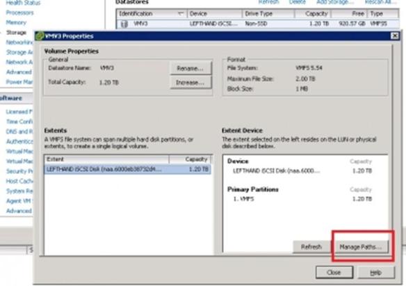
9-27-2011 17:27:36 上传
可以看到默認的Path策略是Fixed(VMWare) – 【固定】,
在下面的路徑資訊中可以看到路徑C1的Status為Active(I/O),
並在Preferred(首選)中標注了*, 而路徑C0的Status為Active,
Preferred中沒有標注*這個策略是不能實現負載均衡的.
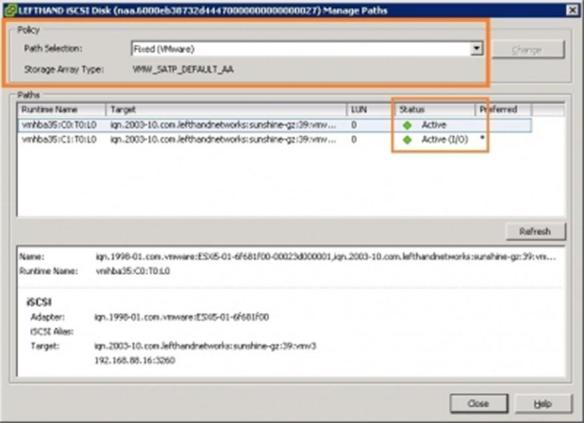
9-27-2011 17:27:37 上传
將策略改為Round Robin(VMWare) – 【迴圈/輪轉】
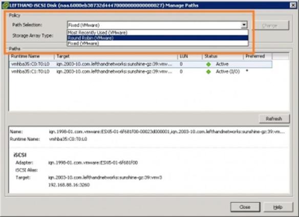
9-27-2011 17:27:37 上传
修改完成後可以看到:路徑C1和C0的Status都為Active(I/O),Preferred中都沒有標注*
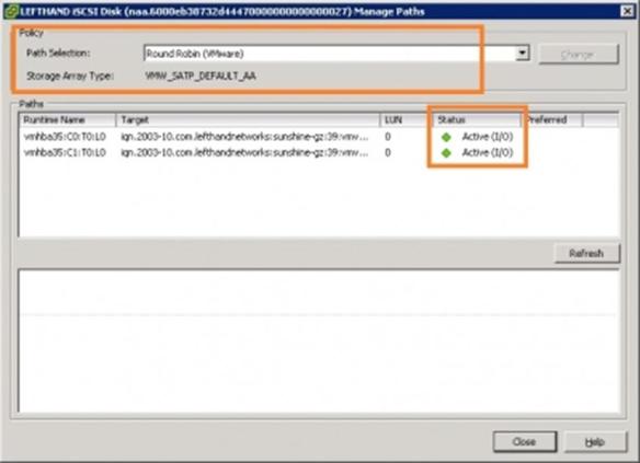
9-27-2011 17:27:38 上传
至此,設置基本完成,測試一下多個VM的I/O,可以看到由原來的集中於vmnic2的I/O,現在平均分佈到
vmnic2/vmnic3兩者當中。
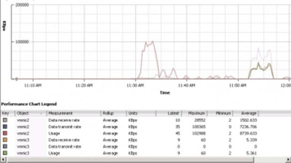
9-27-2011 17:27:35 上传
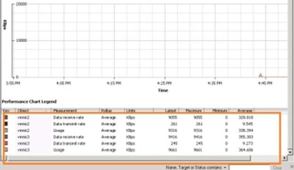
9-27-2011 17:27:39 上传
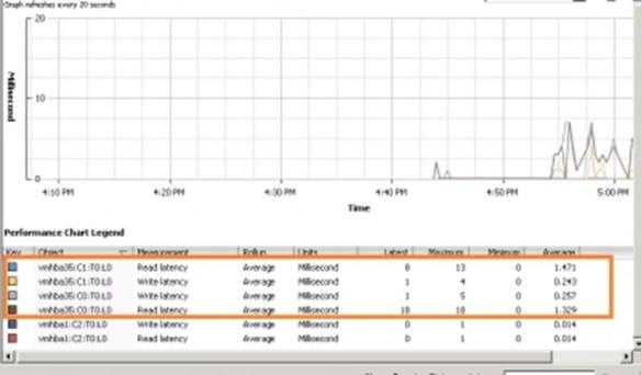
9-27-2011 17:27:11 上传
鏈路負載均衡策略除了以上的基本設置,還可以通過2個主要參數進行細調,
以符合不同的要求或環境。調整Round Robin策略通過命令列進行操作:
設置完預設的Round Robin策略後,以命令列模式執行
esxcli storage nmp device list
可以看到Round Robin策略的默認設置,其中紅字處標明了當前啟用的策略及其應用參數:
naa.6000eb38732d44470000000000000027
Device Display Name: LEFTHAND iSCSI Disk (naa.6000eb38732d44470000000000000027)
Storage Array Type: VMW_SATP_DEFAULT_AA
Storage Array Type Device Config: SATP VMW_SATP_DEFAULT_AA does not support device configuration.
Path Selection Policy: VMW_PSP_RR
Path Selection Policy Device Config: {policy=rr,iops=1000,bytes=10485760,useA NO=0;lastPathIndex=0: NumIOsPending=2,numBytesPending=36864}
Path Selection Policy Device Custom Config:
Working Paths: vmhba35:C0:T0 0, vmhba35:C1:T0
 0
0
VMW_PSP_RR說明當前啟用了Round Robin策略
2個主要的參數 iops=1000, bytes=10485760
前者限定在進行1000次io操作後切換到下一個路徑,後者限定在發送10485760位元組的資料後切換到下一個路徑
可以通過以下命令列來修改這2個參數的值,以符合不同的要求或環境。
修改iops參數:
esxcli storage nmp psp roundrobin deviceconfig set –type=iops –iops 888 –device naa.xxxxxxxxxxxxxxxxxx
修改bytes參數:
esxcli storage nmp psp roundrobin deviceconfig set –type “bytes" -B 12345 –device naa.xxxxxxxxxxxxxxxxxx
iSCSI LUN的UUID(naa.xxx)可以通過命令: esxcli storage core path list 獲取
有很多人關心Jumbo Frames的設置,那就補充一下:
要設置 Jumbo Frames,打開連接iSCSI SAN的vSwitch(vSwitch2)的屬性,在這裡你可以針對整個vSwitch2(All Port)
做JF修改,也可以只針對其中所有設置了MPIO的iSCSI VMkernel(port group)做JF修改。
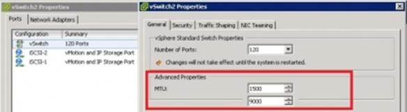
9-28-2011 10:45:03 上传
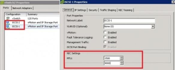
9-28-2011 10:45:02 上传
注1:要能實際啟用Jumbo Frames,整個iSCSI鏈路的所有連接設備(網卡/OS or Hypervisor/交換機/存儲端)都要支援和啟用JF,
才能實現效果。另外,不是所有的設備或環境下啟用Jumbo Frames都能帶來很大性能的提升,建議以自己的評估測試結果
來決定是否啟用。
注2:另外要提醒一點,如果VM中設置了MSCS群集服務,MSCS不能通過設置為Round Robin策略
的路徑來連接MSCS共用盤,否則會出現I/O錯誤。
VM VCB & VDR Collection
VM Backup
淺談VMWare虛擬環境架構下的備份方式
在VMware虛擬環境架構中,常見的備份主要有四種,分別為:傳統備份方式、VMware
Consolidated Backup (VCB)、VMware Data Recovery (VDR)、儲存裝置備份方式。
傳統備份方式:
這種備份方式是將每一個虛擬機器當作實體機器來看待,在每個虛擬機器中安裝所需要的
備份代理程式,並透過既有的成熟備份方案進行作業。優點:
1. 可沿用過去所使用的備份解決方案。
2. 減少資訊管理人員額外的備份教育訓練需求。
缺點:
1. 因為需要在每個虛擬機器安裝備份代理程式,傳統的計價方式可能會造成成本過高。
2. 備份時將嚴重影響線上機器的運作效能(包含其他在同一部實體主機上的虛擬機
器)。
3. 無法充分利用HA、DRS、vMotion等技術帶來的好處。
4. 還原可靠度備受考驗,需不斷進行災害復原演練確保還原作業可行。
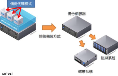
VCB備份方式:
VMware Consolidated Backup (VCB)為VMWare所提供的一組Framework,可透過第三方備
份軟體(如:Symantec Back EXEC 2010、Vizioncore vRanger Pro、Veeam、PHD
esXpress)或VCB指令,並結合虛擬機器快照及FC / iSCSI傳輸技術來進行備份作業。
其備份動作簡述如下:
1. 凍結虛擬機器,並進行應用程式一致性備份(VSS)。
2. 進行虛擬機器快照作業。
3. 解凍虛擬機器。
4. 將快照檔案載入至備份代理伺服器。
5. 執行備份作業。
6. 移除虛擬機器快照檔案。
VCB
使用VCB備份方式帶來的優點很多,簡述如下:
1. 透過備份代理伺服器,可減低ESX主機的負載(甚至可達到零負載)。
2. 不需要在每個虛擬機器上安裝備份代理程式,可減輕管理負擔及減少軟體授權費用。
3. 透過SAN的傳輸,可大幅減少備份時的網路負載。
4. 可做到映像層級及檔案層級的備份,亦即可完整備份整個系統,也可還原單一檔案。
5. 減少備份所需的時間。
依照系統架構的不同,VCB運作的方式可分為三種,分別為SAN模式、Hot Add模式、
NBD模式,簡述如下:
VCB SAN模式:
1. 需要有SAN儲存裝置架構。
2. 備份代理伺服器直接透過FC / iSCSI讀取SAN資料內容。
3. 效能最高、系統負載最小、不會產生額外網路流量
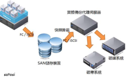
VCB Hot Add模式:
1. 使用虛擬機器作為備份代理伺服器。
2. 無需將儲存裝置的LUN對應到備份代理伺服器。
3. 可備份該ESX主機上的本機磁碟區及NAS存放裝置(如需備份多台ESX主機上的儲存
裝置,需在各ESX主機上安裝備份代理伺服器)。
4. 會消耗ESX主機資源,備份效能低於SAN模式。
簡單說明如下圖:
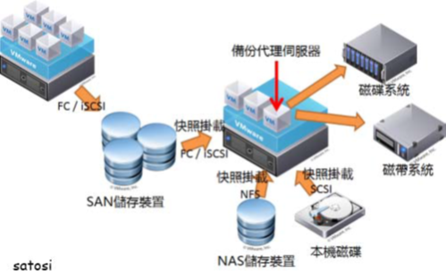
VCB NBD模式:
1. 無SAN儲存裝置架構。
2. 透過網路進行備份傳輸(支援加密傳輸模式)。
3. 備份代理伺服器可安裝於實體機器或虛擬機器。
4. 效能低於SAN模式及Hot Add模式,但仍高於傳統備份方式。
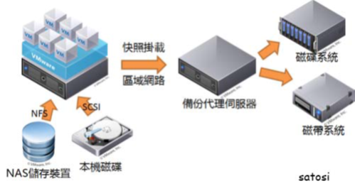
VDR備份方式:
VMware Data Recovery (VDR)為VMWare自vSphere開始加入的一項備份軟體。
提供於vSphere Essentials Plus、Advanced、Enterprise、Enterprise Plus,其備份原理類似於
VCB,支援100個虛擬機以下的備份,適合於中小型的虛擬環境中使用。
VDR為運作於虛擬環境中的虛擬主機,透過VMWare提供的OVF格式進行安裝佈署,其作
業系統平台為CentOS Linux。
優點如下:
1. 無需額外的軟體及備份代理程式費用,很適合中小型環境使用。
2. 虛擬機器無需安裝任何備份代理程式。
3. 支援增量備份方式(強制啟用)。
4. 整合vCenter Server排程備份作業。
5. 提供資料重複刪除技術(磁碟映像等級)。
6. 可進行檔案層級還原(實驗階段,僅支援Windows平台)。
缺點如下:
1. 只支援本機、NAS儲存裝置、SAN儲存裝置,不支援磁帶備份。
2. 至多同時支援兩個目標儲存區。
3. 目標儲存區容量限制(網路磁碟500GB、本機磁碟1TB)。
4. 只支援vSphere主機,無法支援ESX 3.5主機。
儲存裝置備份方式:
透過SAN儲存裝置的複寫機制進行備份,如NetAPP SnapMirror、IBM Enhanced Remote
Mirroring、Metro Mirror等,透過此種備份方式可達到最佳的備份效能,並能透過VMWare
Site Recovery Manager完成異地備援架構。
儲存裝置備份一般分為三種方式,簡述如下:
同步複製模式:
1. 主站點需收到遠端站點的I/O回報後,才算完成整個I/O作業。
2. 同步模式適用於高度資料保全要求或機房內部使用,此模式不會產生資料遺失。
3. 因同步模式需等待遠端站點的I/O回報,因此整體運作效能較低,也會受限於頻寬及
距離的限制。
非同步模式(無一致性):
淺談VMWare虛擬環境架構下的備份方式 « SaSa白 ✕ 技術隨筆手札頁 4 / 6
1. 主站點完成I/O後即算完成整個I/O作業,不需等待遠端站點的回報。
2. 非同步模式適用於大多數的情況。
3. 不保證備援端與主站點有相同的I/O順序。
4. 非同步模式斷線時可能會造成部分資料遺失,需視網路頻寬及距離而定。
5. 非同步模式整體效能高於同步模式,亦較不受頻寬及距離的限制。
非同步模式(一致性):
1. 其運作方式與非同步模式(無一致性)相同,差別在於可保證備援端與主站點有相同
的I/O順序。
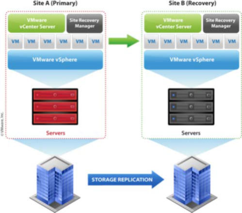
Good Article For SNAPSHOT NOTES
大家在用虛擬機器的時候最最看重可能就是虛擬機器的快照功能了,做個快照,然後隨便開始整就算系統壞了,在用快照恢復一
下就OK了,多好的技術呀。但是請記住快照不等於備份,千萬不要把快照當作備份。
當虛擬機器開著時,快照提供了一個備份原始VMDK檔的好辦法。所有的寫入操作在原始檔上暫停了,因此,複製它在另
一個存儲卷很安全。這就是像
VMware Consolidated Backup和Vizioncore的vRanger功能那樣的備份應用。它們給虛擬機器進
行快照、備份磁片檔並在完成時刪除快照。
諸如VMBK這樣的腳本也提供這種功能。這些程式允許複製VMDK檔到本機存放區或網路共用以提供另一種恢復重要虛擬機器
的方法。
只有一個快照的虛擬機器在刪除快照時不需要額外的磁碟空間。不過如果你有許多快照,當刪除所有快照時,你將需要額外的
磁碟空間。這是由於這些快照要合併到原始磁片檔。
例如,假設你要刪除有三個快照的虛擬機器上的所有快照,我們稱它們為快照1、快照2及快照3。首先,快照3將合併到快
照2,快照2的大小將增加。接下來,快照2合併到快照1,快照1的大小也將增加。最後,快照1將合併到原始磁片檔,這
不需要額外的磁碟空間。當原始磁片檔在整個操作結束時更新,快照檔被刪除,而不是每個合併過程時刪除。因此,當
刪除它們時,擁有20GB快照檔的虛擬機器可能需要額外的20GB。
( NEW Method When delete all snaopshots all delta direct copy to Base Image)
如果你有一台低磁碟空間的ESX主機,這將用光所有可用的磁碟空間,並且阻止你刪除快照。
使用較少額外磁碟空間來刪除多個快照的解決辦法是一個一個刪除它們,從虛擬機器父級快照開始到子級。使用這種方法,當
快照被合併到先前的快照,只有先前快照增加了,然後刪除。這個方法雖然沉悶,但不需要較多的額外磁碟空間。
注意:當虛擬機器有一個快照運行時,不要運行Windows磁片磁碟重組。磁碟重組操作改變許多磁片塊並能引起快照檔急
速增加。
多長時間刪除快照當使用VMware Infrastructure Client(VI Client)刪除快照時,這個任務狀態列容易使人誤解。一般來說,任務狀態跳
到95%完成率時應該很快完成,不過能注意到它在95%一直不動,直到整個刪除過程完成。VirtualCenter有15分鐘的超時時
間。因此,就算你的檔仍然在刪除,VirtualCenter將報告這個操作超時. 找到任務完成的方法是使用VI Client裡的資料存
儲流覽器查看虛擬機器目錄。當delta檔消失了,你就知道快照刪除完成了。
活動了很長時間的快照(因此變得很大)在刪除時需要很長時間。快照刪除需要的時間的變化取決於虛擬機器活動等級;當關
閉虛擬機器時,刪除時間短。ESX主機上的磁片子系統活動數量也能影響快照刪除時的時間。100GB的快照需要3到6小時合併
到原始磁片。
使用ESX 3.5的話,由於整合演算法的變更,將需要更長的時間。這將影響虛擬機器和ESX主機的性能。正因如
此,你應該限制保留快照的時間長度,在你不需要它們時就刪除。
快照和遠資料鎖定影響ESX性能
快照對ESX主機和虛擬機器的影響有幾種方式。當你第一次創建一個快照時,虛擬機器活動將暫時停止;當創建快照時,如果虛
擬機響了,你將注意到超時。同樣,創建快照引起中繼資料更新,將導致SCSI預留衝突以致鎖定LUN(邏輯單元號)。結果,
在一小段時間裡,LUN只能在ESX Server主機上可用。
如果你創建了個虛擬機器快照並運行虛擬機器,這個快照是活動的。如果這個快照是活動的,由於ESX有區別地寫入delta檔,
不如寫入標準的
VMDK檔那樣有效率,虛擬機器性能將降低。由於中繼資料鎖定了,當一個寫入到磁片時,其他的都不能寫入
到delta文件。
同樣,隨著delta檔以每個
16MB增量增加,將引起另一個中繼資料上鎖。這能影響虛擬機器和ESX主機。
性能影響有多大取決於虛擬機器和ESX主機有多繁忙。
最後,刪除一個快照也創建一個中繼資料鎖定。另外,當delta檔正被commit時,你正刪除的快照將造成虛擬機器性能的大幅
度下降。如果虛擬機器非常繁忙,這將很容易看到。為避免這個問題,最好在主機伺服器不繁忙的閒時刪除大的或多個快照。
當快照運行時不要擴充磁片檔
當一個快照是活動的時候不能擴充虛擬磁片。在ESX 3.0.x,你只能使用vmkfstools——X command擴充磁片;不過,當你試
圖擴充磁片時,這個指令不會警告你磁片擁有快照。你也可以通過VI Client擴充虛擬磁片,VI Client允許你使用快照擴充磁
盤。VI Client將成功地報告任務完成,不過實際上卻沒有擴充磁片檔。
當一個快照活動時,如果你使用vmkfstools擴充虛擬磁片,虛擬機器將不再工作並出現錯誤:“不能打開磁片‘.vmdk’或在它之
上的一個快照磁片。
拒絕虛擬磁片使用快照如果你的一台虛擬機器有多個磁片,你希望拒絕一個磁片使用快照,你必須通過改變磁片模式為獨立來
編輯虛擬機器設置。獨立設置能讓你獨立地控制每個磁片的功能,磁片檔和構造沒有區別。一旦一個磁片是獨立的,它將不
包括任何快照。
另外,你將不能在擁有獨立磁片的虛擬機器上包括存儲快照。這麼做是為了保護獨立的磁片,萬一你恢復到先前的有存儲狀態
的快照,有一個寫入獨立磁片的應用在運行。當其他磁片在恢復時,由於這個獨立磁片沒有恢復,在它上面將有潛在的損壞
數據。
vSphere Data Protection replaces VDR with vSphere 5.1
vSphere Data Protection replaces VDR with vSphere 5.1
This new backup product replaces VMware Data Recovery, which has been introduced in vSphere 4.0 and which will still be supported. But from vSphere 5.1 the vSphere Data Protection (VDP) is going to be The Backup product bunled with vSphere.
The VDP has the most of the code from EMC’s Avamar backup product and in fonctionnalities. It’s has more or less the same functions as VDR, (no fancy “Run VM from backup") but much more robust than VDR, and including features that can even rollback the appliance to previous point in time. The backup limit per appliance is 2 Tb and you can have up to 10 VDP appliances managed by single vCenter with tight integration into the New vSphere 5.1 Web Client.
It’s agent-less and disk based backup architecture, which uses vSphere API for Data protection (VADP) with Changed Blocks tracking (CBT) … like VDR does, but there is also some Avamar goodnes there. The appliance uses an EMC’s Avamar variable-length segment de-duplication engine to optimize backup and recovery times. De-duplication is used not only within each VM, but across all backups jobs and all VMs being backed up by the VDP appliance.
Initial backups take a fair amount of time, but subsequent backups can be as little as a few minutes depending on the number of changes that have occurred since the last backup. CBT tracks the changes made to a VM at the block level and provides this information to VDP so that only changed blocks are backed up. VMware Tools on Windows VMs are using Volume Shadow Copy Service (VSS) components to assist with guest OS and application quiescing when backing up Windows VMs.
What are the new functionality and how the product is delivered to the end user?
The VDP is a virtual appliance which is available in 3 sizes for the destination datastores, which will be as in the case of VDR, be used as a deduplication store, to store the backups. So the destination datastore can be configured in 3 sizes:
– 500Gigs, 1Tb, 2Tb
The actual virtual appliance which runs the Suse Linux Enterprise Server 11 (SLES) runs with 4 vCPU and 4 Gigs of RAM. During the deployment process, the thick disks are used, and those disks consume 850 GB (3 .vmdk files), 1600 GB (7 .vmdk files), and 3100 GB (13 .vmdk files) respectively. To create the necessary deduplication destination datastore, which will be used later for the target of the backup jobs.
The VDP appliance can be managed only by vCenter Server 5.1 through web client. VMware is shifting away of the “thick" client so the management of backups through the vSphere Client is possible only through the new vSphere Web Client. And there is no plugin for the “thick" client anymore…. Curiously, the plugin for vSphere Update manager (VUM) hasn’t been released at the same time, but AFAIK the integration of VUM will follow in the days to come.

It’s possible to make a backup of powered Off VMs, since no agent is installed inside of backed up VMs.
The management through web client – relaying on Flash – good or bad – The management of the appliance is only possible through supported browsers. Currently supported browsers: IE 7, 8 on Windows. Firefox 3.6 and higher on Windows or Linux. Adobe Flash is required, it means that MAC iOS users can’t manage this backup solution (unless they Install VMware Fusion and Windows or Linux VM).
Update: The MAC users can of course use alternate browser supporting Flash plugin. (Firefoex, Chrome).. I’m using Chrome, because ist’s so fast.
The Backup/Restore/Schedulling Possibilities – The Possibilities are about the same as we use to have with VDR, but the product seems to me more robust…. more professional looking and hopefully more reliable than VDR was.
The Sizing of the VDP’s has to be done before the deployment – When deploying the solution, you must think before on what size you’ll need at the destination deduplication datastore since this size cannot be changed later. The same as in VDR.
Here is a screenshot what it looks like just after the deployment of the appliance. The “maintenance mode".
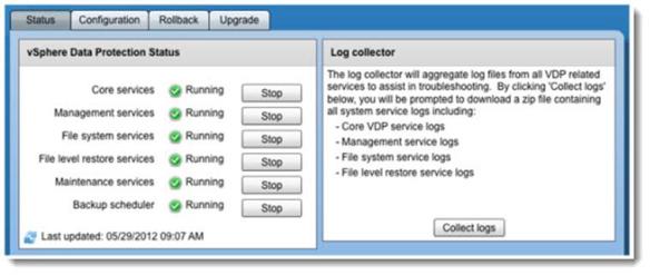
Backup/restoration jobs and scheduling – those tasks are Wizard driven and permits the configuration of backup job. In the UI There are containers such as data centers, clusters, hosts, folders, etc. An individual VMs can be selected for backup. If new VMs are added to a container that is currently backed up (backup job has already been configured), these new VMs will automatically get backed up on the next run of the backup job.
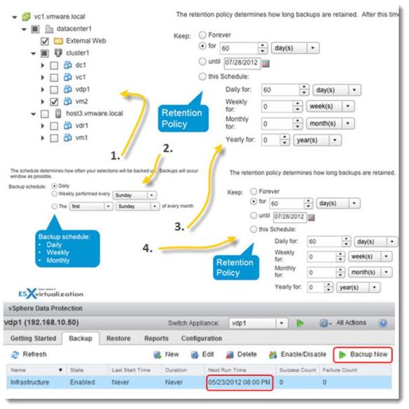
The restore operations – to restore a VM, it seems that the UI stays fairly similar (if not the same) with VDR. There is possibility to restore full VM or FLR (file level restore), by selecting the restore point. Also wizard driven, it’s necessary to provide a name for the restored VM and a location. There is checkbox which enables to select the original location as a restore location.
But again, compared to VDR, the product seems just more mature and more robust, giving you for example more choices when restoring individual files from VM image.
There are some requirements for the FLR though, like the VMware Tools installed inside of the VMs and the file Systems supported (currently Windows NTFS and Linux LVM, Ext 2, Ext 3 and basic disks – non-extended).
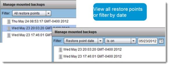
Monitoring restore jobs – there is a possibility to monitor restore jobs, by clicking the Monitor Resources button, and see the progress of the restore operations.
8 mount points mounted simultaneously – another thing is that you can mount more than one restore point simultaneously (eight maximum), which can helpful if you are not sure of the exact version/date of the file you need to restore.
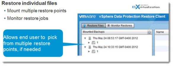
Advanced Login Possibilities – 2 ways of login (basic and advanced). The basic login uses local credentials only. The basic login can be used by owners of the VM for example to restore the files inside of that particular VM only.
As for the advanced login, the admin has the possibility to restore files from a VM elsewhere. The advance login requires credentials with administrative permissions on the local machine and credentials with administrative permissions on vCenter Server.
Locking and unlocking backup images – this might be useful for keeping restore points for archiving purposes. The restore point is kept even the retention policy says that the restore point should be deleted.
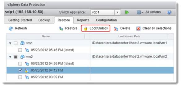
Reporting capabilities – The VDP has a reporting TAB which provides several pans, which shows each detailed information about the appliance’s status, the status of the backup jobs, the storage capacity, the success (and failures) of backup/restoration jobs.
There are possibility to create filters on specific criterias like VM, last backup date, last backup job occurred within x number of days, etc.
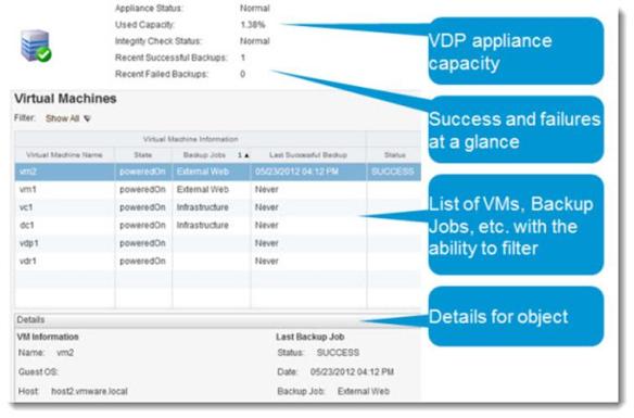
E-mail Reporting – the application provides e-mail reporting capability, which can be schedulled daily at specific time. You can also change the default English language to specific locale (which is pretty nice for customers wishing to receive this information in french, Dutch, or Japanese language).
Backup and Maintenance window – the backup window (Green) runs by default from 8:00 PM to 8:00 AM, the blackout window (Black) blackout window runs from 8:00 AM to 11:00 AM, and the maintenance window (yellow). During backup window the backup jobs can run only. The jobs starts at the beginning of backup window automatically (up to 8 jobs simultaneously – per appliance). If the job overlap the backup window, the job fails.
When the VDP appliance is first deployed and configured, the maintenance services are disabled for the 24-48 hours. This allows for a longer backup window to support the initial backups, which are full backups.
– What is the Blackout Window? – During the blackout window the Garbage collection deletes orphaned chunks of data that are no longer references within any backups on the system. Only restores can be executed, but no other (including administrative) activity can be performed.
– Maintenance window – there are integrity checks, which progress is stored in VDP appliance itself. If the process has not finished at the end of maintenance window, it will be picked up the next day, where it left off. You can also force the Integrity checks manually, but obviously the tasks are Full Integrity Checks.
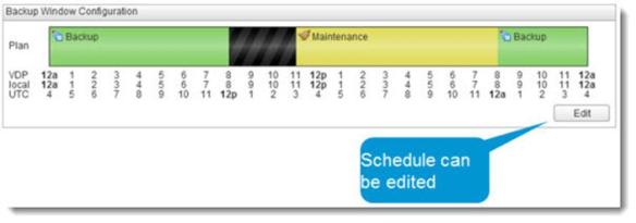
The Integrity checks which runs in the maintenance window are verifying the integrity of deduplication stores. are two types:
– Full: Checks the entire de-duplication store.
– Incremental: Checks the checkpoints since the last full or incremental integrity check.
VDP Rollback and Checkpoints – this feature that I mentioned at the beginning, helps you (if needed) to restore the appliance to the previous point in time (like in windows, the system restore application).
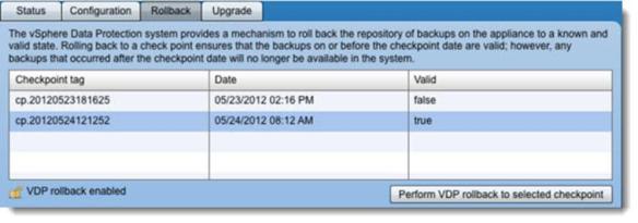
The VDP appliance uses EMC’s Avamar deduplicaiton technology which should perform more smoothly and more efficiently than the VDR. The VDR will still be supported but further developpement was stopped.
I haven’t seen any way to import existent jobs or deduplication stores into VDP….. Any suggestions here from VMware? Are the thousands of customers left to themselves here? Is the only way to setup the new product by re-creating new jobs for your virtual infrastructure?
In my opinion, VMware did a good job here to replace the VDR, since there has been quite a problems with the stability and reliability of VDR.
VMware vSphere 5.1 – More about VMware vSphere 5.1 news from the launch
vSphere 5.1 – New features and enhancements
- VMware vSphere 5.1 – Virtual Hardware Version 9 (August 27, 2012)
- vSphere Data Protection – a new backup product included with vSphere 5.1 (This post) (August 27, 2012)
- vSphere Storage Appliance (VSA) 5.1 new features and enhancements (August 27, 2012)
- vCloud Director 5.1 released – what’s new (August 27, 2012)
- vSphere Web Client – New in VMware vSphere 5.1 (August 27, 2012)
- vSphere 5.1 and New VMware Enhanced vMotion (August 27, 2012)
- vSphere 5.1 – New Features and Enhancements in Networking (August 27, 2012)
- VMware SRM 5.1 and vSphere Replication – New release – 64bit process, Application Quiescence (August 27, 2012)
- Top VMware vSphere 5.1 Features (August 27, 2012)
- vSphere 5.1 licensing – vRAM is gone – rather good news, any more? (August 28, 2012)
- Coolest VMworld Videos (August 29, 2012)
- Further on VMware’s New Licensing (August 30, 2012)
- ESXi 5.1 Free with no vRAM limit but physical RAM limit of 32Gb (September 3, 2012)
TCP/IP FSM & Wait-Time
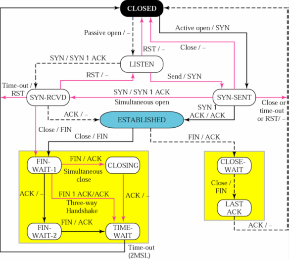
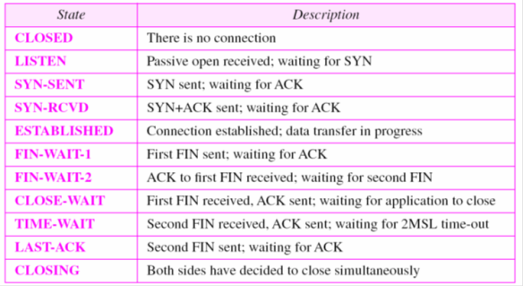
TIME WAIT